
Changelog
August 12th, 2021: Publication of the original article
Introduction
This is the first article of a Do It Yourself (DIY) series in which I describe simple electronic projects that make use of an ESP8266/ESP32 board running the Tasmota firmware to integrate various modules into a home automation system, such as Home Assistant. In this first iteration of the series, I described how to wire and configure a BME280 to the tiny ESP-01 (or its successor, the ESP-01S) to create a cheap (less than US$6), low-power (less than 1W), and low-profile (less than 5cm long) environmental sensor that provides temperature, humidity, and relative pressure measurements to home automation systems via MQTT.
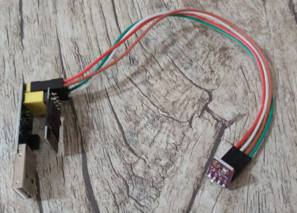
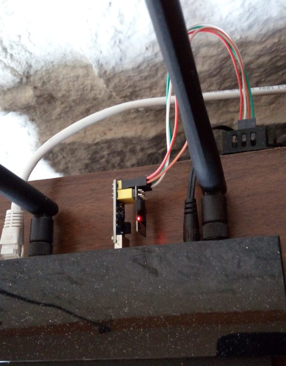
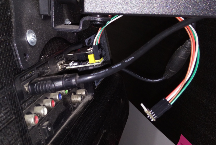
- Here is a preview of the ambient sensor alone and attached to different devices:
This is a great project for anyone who wants to get started on building their own Internet of Things (IoT) devices. The article started with my motivation for this particular project. Next, I talked about the hardware and software components, and finally, at the end, I covered the assembly of it all to create a functional unit.
Because this is such a low-profile project, I do not ever bother printing a case for it. However, if you designed a case to house this particular project, get in touch with me and I will feature your case here. But please observe the official mounting instructions for the BME280 sensor before printing your case because the heat generated by the ESP-01 and its USB adapter can affect the sensors.
Motivation
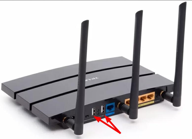
Over the years, I have started noticing that multiple devices spread across the household (e.g., smart TVs, sound systems, wireless routers, PC towers and laptops) had one or more USB ports that could be used to power a few DIY electronic projects.
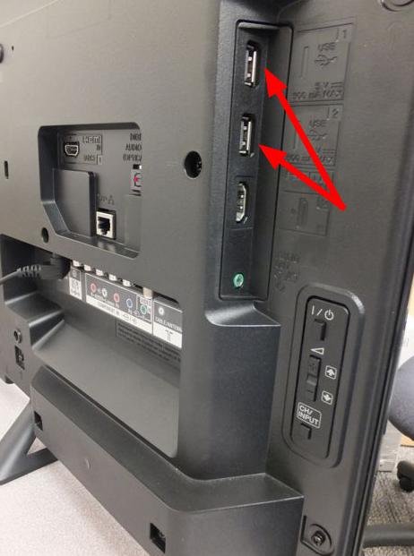
However, the most common type of USB port available (USB 2.0) usually delivers a maximum of 500mA at 5V (2.5W), which constraints the type of projects that could reasonably use such ports as power supply. In addition, because interfacing via the USB connection might not always be possible, owing to proprietary and closed-source firmware, the DIY project should be able to transmit data wirelessly instead.
Fortunately, the ESP-01 WiFi module meets all such requirements. Specifically, it requires very little energy to operate (roughly .3W on average, with 1W peaks) and can be connected to USB 2.0 ports via USB adapters that have a built-in voltage regulator.
Furthermore, because the unit will draw power from standard USB ports, it can be connected to most power banks to create a mobile/remote ambient sensor.
Overview of the main hardware components
ESP-01
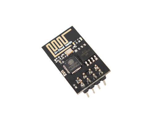
The ESP-01 is a cheap and very small WiFi module developed by Ai-Thinker that is based on the ESP8266EX microcontroller unit (MCU) by Espressif:
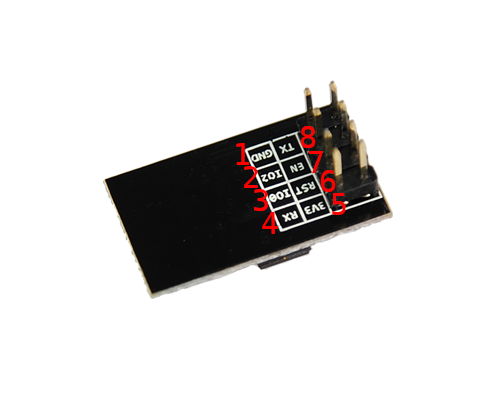
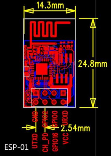
Of note, it exposes only four GPIO pins to interface with other devices–namely, URXD, UTXD, IO2 and IO0–and it is powered via 3v3 DC to the VCC and GND pins. Each of the eight exposed pins has specific functions, as suggested by their name:
| Pin # | Names | Functions and notes |
|---|---|---|
| 1 | GND | Ground |
| 2 | IO2 | GPIO 2, internal pull-up |
| 3 | IO0 | GPIO 0 (zero), internal pull-up |
| 4 | URXD / IO3 | UART0 - serial RX data, GPIO 3 |
| 5 | 3v3 / VCC | 3.3V power supply |
| 6 | RST / IO16 | Reset pin, active low |
| 7 | EN / CH_PD | Chip enabled pin, active high |
| 8 | UTXD / IO1 | UART0 - serial TX data, GPIO 1 |
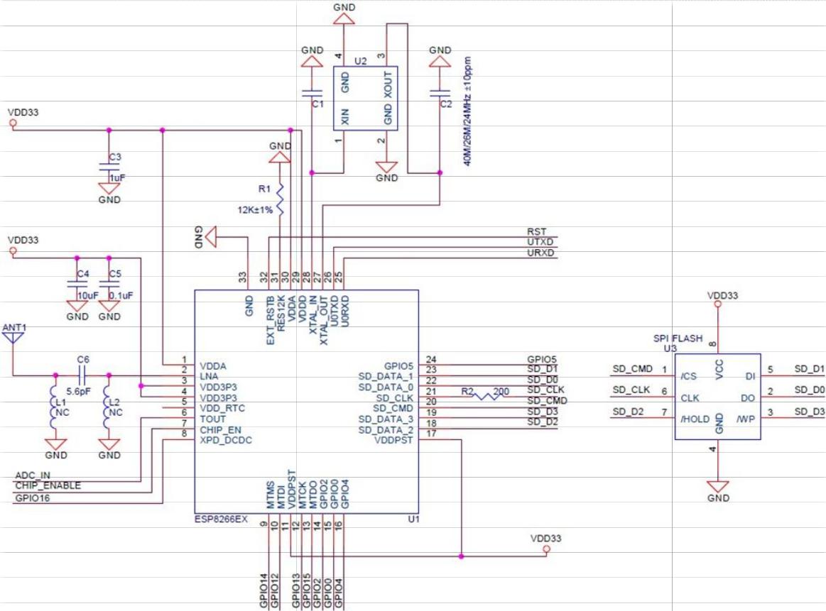
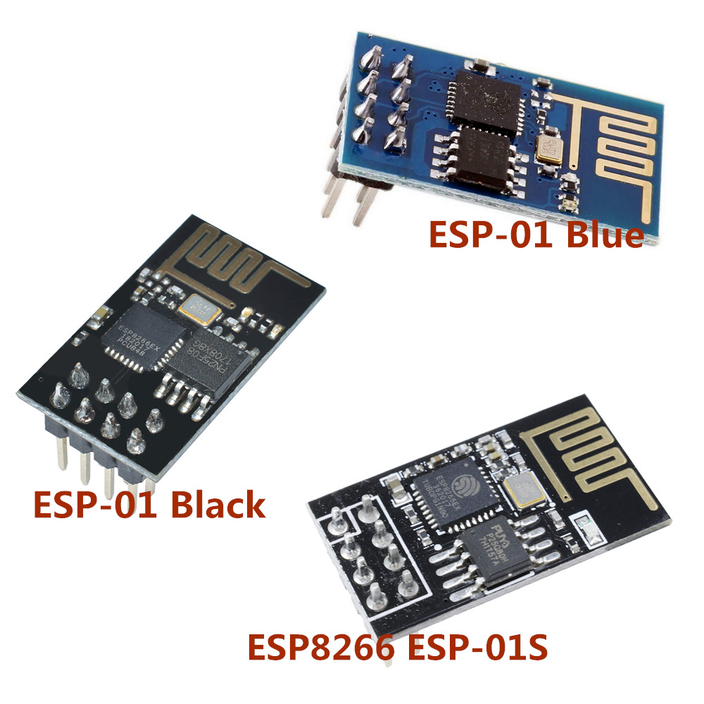
In addition, there is no programmable ROM in the SoC, meaning that any software must be stored on the module’s SPI flash. Regarding the latter, there are actually three popular versions of the ESP-01 WiFi module that have the same format but differ in flash memory size or other minor specs:
- ESP-01 Blue: The original version with
512KBof flash memory; - ESP-01 Black: The original version with
1MBof flash memory; - ESP-01S: A revised version with
1MBof flash memory.
Fortunately, visual inspection of the module can easily indicate which version it is:
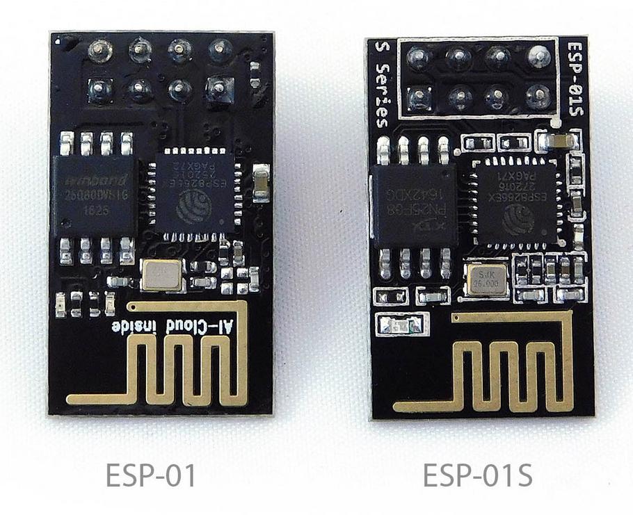
The external SPI flash can be changed for anything up to 16MB. However, this requires de/soldering very small components and such procedure won’t be covered in this guide (but see Andreas Spiess’ video #34 for reference). My recommendation is to simply look for the versions that have at least 1MB of flash memory, which is just enough for the project described in this article.
For more information, refer to the official documentation:
In fact, Ai-Thinker has developed many other versions of the ESP-01 module, such as the ESP-01E and ESP-01F. However, such modules differ in major aspects in comparison to the modules covered here, like format and connectivity, and for such a reason, they won’t be covered in this article. If interested, check their official e-commerce website at Alibaba.com (https://ai-thinker.en.alibaba.com/) to learn how to acquire those less popular modules.
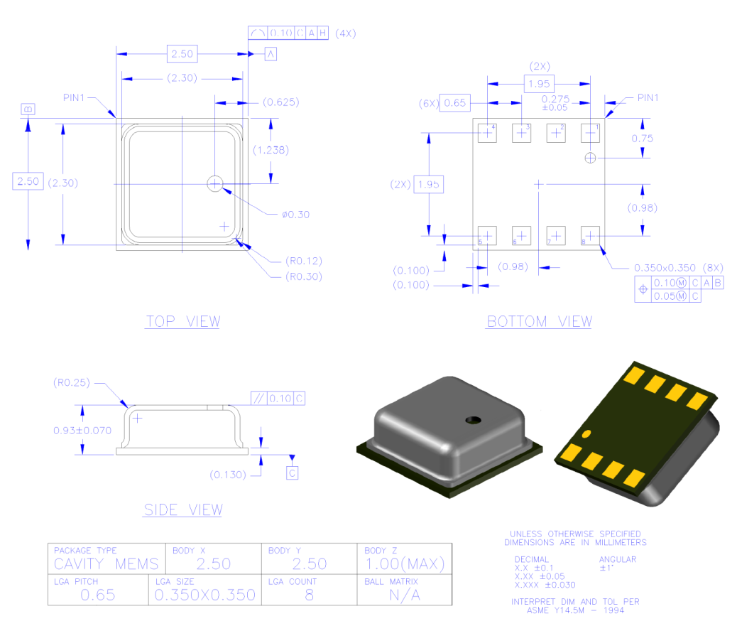
BME280
The BME280 is a low-profile (2.5 x 2.5 x 0.93 mm³) and low-power (3.6 mA at roughly 3.3V) environmental sensor developed by Bosch Sensortec. Specifically, this unit comes with high accuracy sensors for temperature, humidity, and pressure, all protected by a metal-lid. Of note, it uses I²C and SPI interfaces for data communication and is powered by 3v3 DC (specifically, from 1.71V to 3.6V).

Bosch Sensortec has made an amazing job at documenting all aspects about this sensor. For quick reference, here are the main docs:
Hardware
To make a single ESP-01 Tasmota environmental sensor, you will need the following items:
-
01x ESP-01 Black/ESP-01S: These modules are very cheap and useful for simple projects, so I recommend buying multiples at once.
-
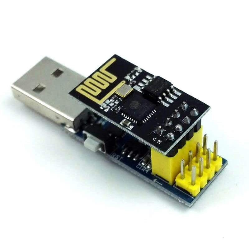
01x USB to ESP-01 adapter: Look for the ones that have exposed pins (see figure below) and preferably, that make use of the Silicon Labs CP2104 (or CP2102) chip. More often than not, however, the adapters will make use of a cheaper and less well-documented chip–namely, a CH340 variation–which might actually work just as well but I have never used them for this same project.
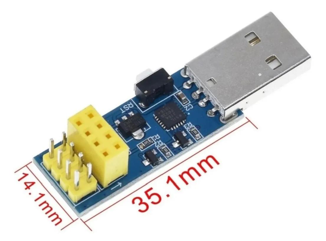
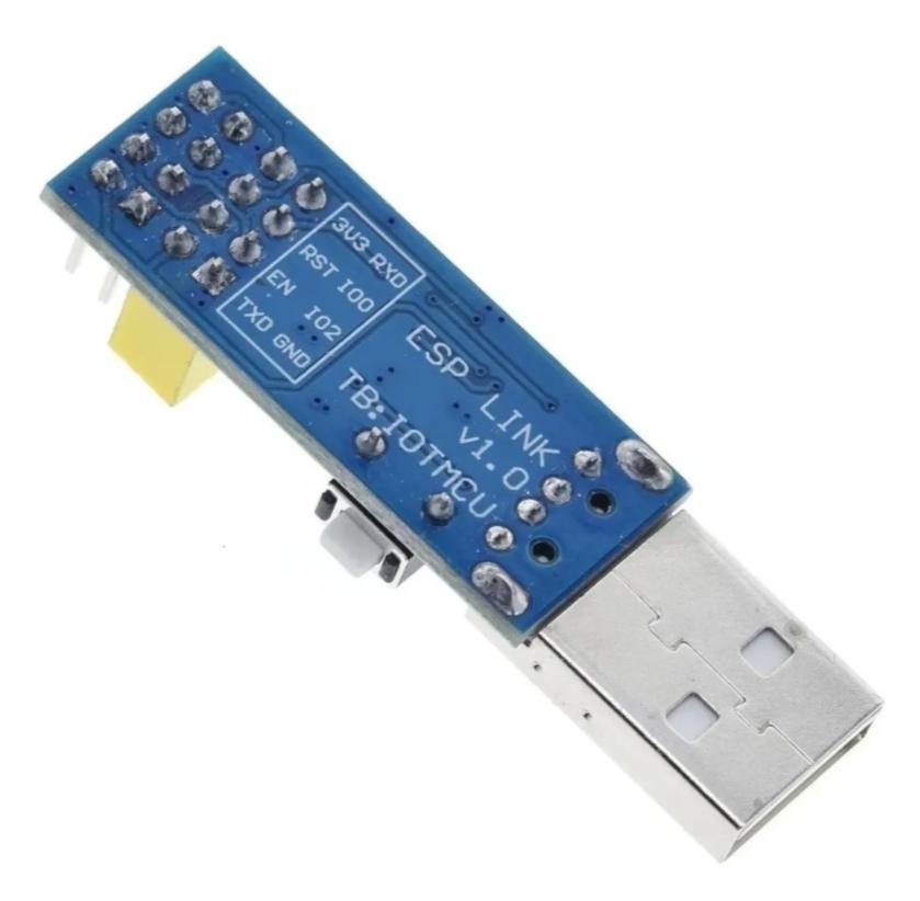
Notice how the exposed male pins are mapped onto the female pins in your own adapter. This is fundamental to figuring out how to put the module into flash mode and later on, how to connect the ESP-01 module to the BME280 module. The advantage of having exposed pins is that no soldering job is required to interface with the ESP-01 module. There are many other options for interfacing and powering an ESP-01 module via USB connections and some provide even cheaper solutions than the one shown here but be prepared to spend time soldering multiple components then.
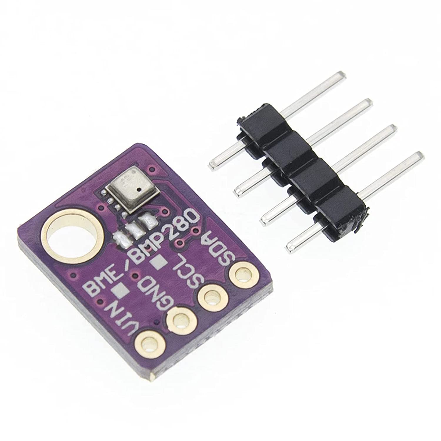
-
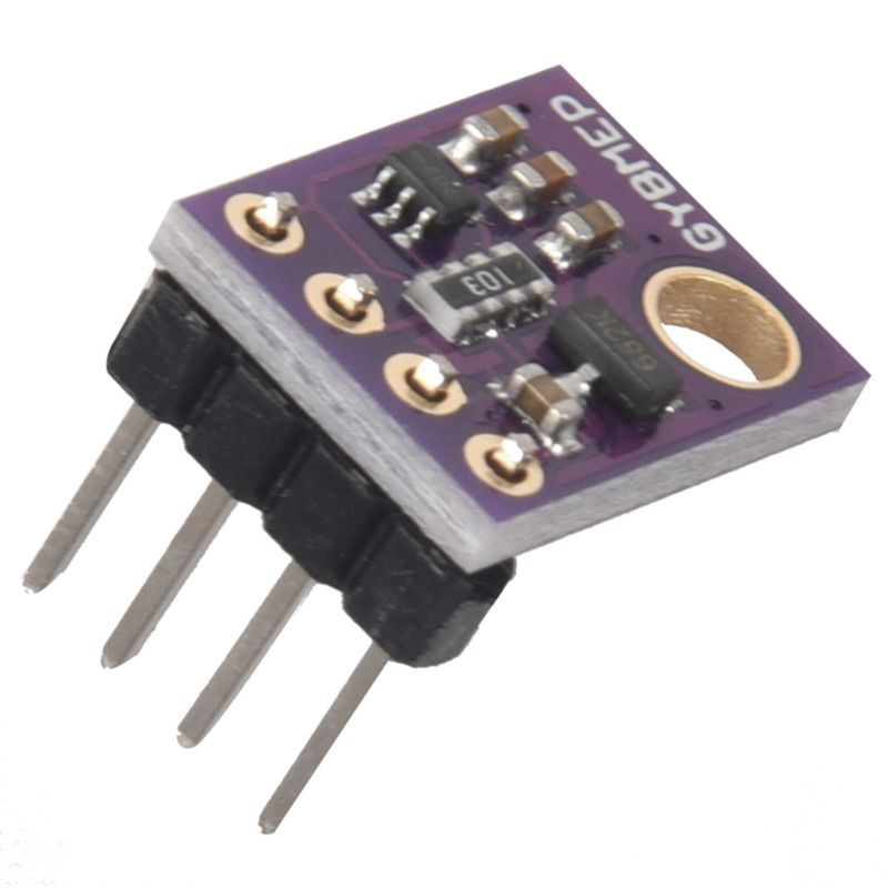
01x GY-BME280 module: You can always buy just the BME280 sensor itself and wire it on your own but it’s much easier to buy a module that contains it instead. The one I used is the one shown in the figures below. More likely than not, you will need to solder the headers to the board (see below). As before, these modules are very cheap, so I recommend to buy multiples.
-
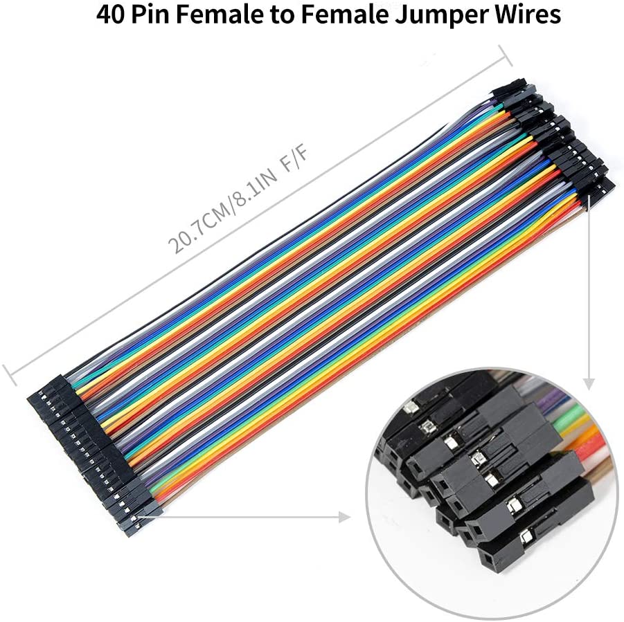
05x Female-Female DuPont/jumper wires: You cannot go wrong by buying lots of these wires in all three connector combinations. For this project, however, you will only need five f-f jumpers (or four, if you reuse one).
-
Optional. Female DuPont connector kit: This is optional but does help securing your connections and make your project look better by housing exposed male pins. I recommend buying a kit with various sizes but for this project, we will only need the following connectors:
-
01x
2x4female connector for the ESP-01 USB adapter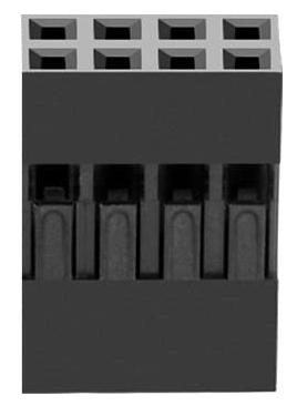
-
01x
1x4female connector for the BME280 module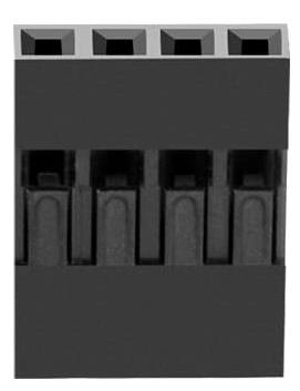
You do not need crimping tools for this. Check the following video for this and other tricks when working with DuPont wires:
-
-
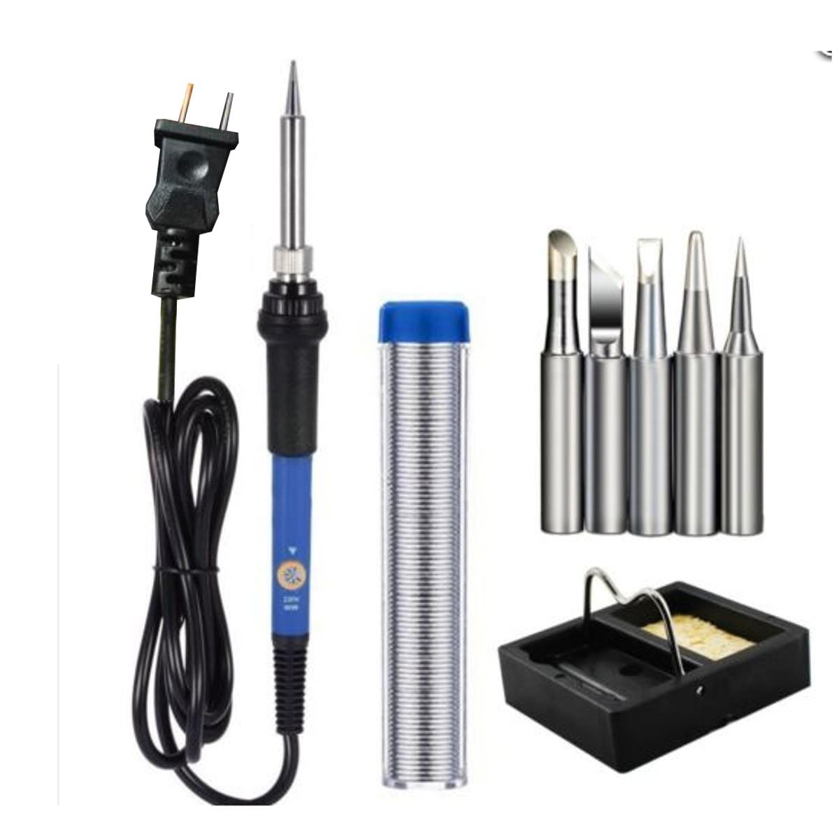
Basic soldering kit: This is only required for soldering the headers to the BME280 module. You do not need anything fancy for this at all. If you have a multimeter, always test your connections afterwards.
Estimated cost
Estimated cost of the basic hardware components:
| Hardware | Quantity | USD$* |
|---|---|---|
| ESP-01 WiFi module | 01 | 1.5 |
| USB to ESP-01 adapter (CP2104) | 01 | 2.5 |
| GY-BME280 module | 01 | 1.5 |
| F-F DuPont 20CM long | 05 | 0.05 |
| TOTAL | - | 5.55 |
* Based on AliExpress.com offers from Chinese stores without including shipping + tax
Software
In this tutorial, we will make use of the following applications:
- Tasmota (
tasmota-sensors.bin)Alternative firmware for ESP8266 and ESP32 based devices with easy configuration using webUI, OTA updates, automation using timers or rules, expandability and entirely local control over MQTT, HTTP, Serial or KNX.
If you have never heard of Tasmota before, check Robbert’s (The Hook Up) introduction video:
- Esptool (
esptool.py)A Python-based, open source, platform independent, utility to communicate with the ROM bootloader in Espressif ESP8266 & ESP32 series chips.
- Optional. Docker
Docker is a set of platform as a service products that use OS-level virtualization to deliver software in packages called containers.
- Optional. Eclipse Mosquitto MQTT broker
Eclipse Mosquitto is an open source message broker that implements the MQTT protocol versions 5.0, 3.1.1 and 3.1. Mosquitto is lightweight and is suitable for use on all devices from low power single board computers to full servers.
Assembly
As in the previous tutorials, this article assumes you are running a Linux distribution (e.g., Debian, Ubuntu, Arch, etc.) and your current user (${USER}) is in the sudo group. Part of the instructions may or may not be compatible with Android, macOS, Windows, or any other Operating System (OS). If you run into issues, please refer to the official documentation of the software mentioned in the Software section.
The Docker and MQTT broker implementation are both optional because Tasmota offers multiple ways to interact with the device without every using the MQTT messaging protocol. In addition, most MQTT brokers offer alternative installation methods to the containerized method described here. That said, I strongly recommend making use of MQTT if you use home automation systems (e.g., Home Assistant, OpenHAB) or have multiple Tasmota devices.
Installing the required packages and fixing user permission
Before we can flash the Tasmota firmware onto the ESP-01, we will need to install a few packages and configure the permissions of the current Linux user to allow using the USB adapter.
-
Open a terminal and install the required packages:
sudo apt update && sudo apt install wget python3 python3-pip -
Install
esptool.pyviapip3:pip3 install esptool -
Find out if
esptool.pycan be found in your user’s$PATH, as follows:whereis esptool.pyAlternatively, when required to run
esptool.py, instead ofesptool.py OPTIONS, run aspython3 -m esptool OPTIONS. If you choose to do this, skip the next step. -
If
esptool.pywas not found, it means your user’s.local/binis not in your$PATH. Add it as follows:echo "export PATH="$HOME/.local/bin:$PATH"" | tee -a "$HOME/.bashrc" > /dev/null -
Connect your ESP-01 to the USB adapter:
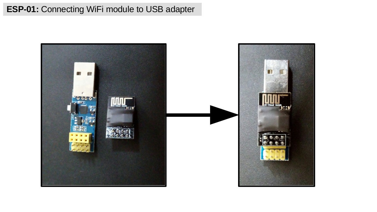
Please ignore the tape over the ESP-01 module. Its use is not necessary.
-
Connect the adapter to a USB port on your computer and check the new device in
/dev/:ls -l /dev/ttyUSB* -
Add your
$USERto the same group as/dev/ttyUSB*(it’s usuallydialoutbut if different, change in the command below) andtty:sudo usermod -aG dialout,tty ${USER} -
Log off and back on. (If you continue to run into permission issues, try rebooting instead. You can check your user’s permissions with
id ${USER}.)
Flashing the Tasmota firmware
We are now ready to flash the Tasmota firmware. For reference, the official information is available at https://tasmota.github.io/docs/.
-
Go to
/optand create atasmota8266directory:cd /opt sudo mkdir tasmota8266 -
Change ownership of the new directory to the current user instead of
root:sudo chown ${USER}:${USER} tasmota8266/ -
Download the latest
tasmota-sensors.binbinary viawgetto the newly created directory:wget -P tasmota8266/ https://ota.tasmota.com/tasmota/release/tasmota-sensors.binAlternatively, you can manually download the latest and previous binaries from the Tasmota Github repo. The URL above points to the latest version of the
tasmota-sensorsbinary. -
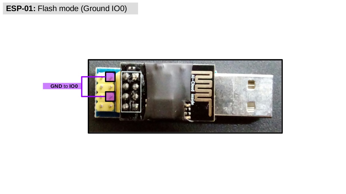
Disconnect your ESP-01 adapter from your computer. Take note of the USB adapter pinout to put your ESP-01 into flash mode by grounding the pin
IO0using a female-to-female DuPont wire, as follows: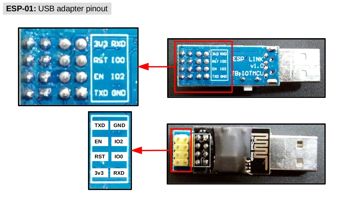
Notice that the pinout is flipped vertically when looking the pins from the bottom vs. the top. For us, it is the top-view pinout that matters because that is where we will connect the DuPont wires. The pinout for your own adapter might not be the same, so make sure to double check before moving on. Once you have a good grasp of the pinout, go ahead put the ESP-01 into flash mode.
-
Reconnect your ESP-01 adapter to your computer. Now find the USB port your device is using in
/dev/and set it to the variableESP_PORT, as follows:Attention. While convenient, the following command assumes there is a single USB to serial adapter connected to your computer. If this is not the case, manually set
ESP_PORTto whichever port your ESP-01 USB adapter is currently using. You can find the port vials /dev/ttyUSB*and testing one by one until you find the one used by the ESP-01 adapter. Alternatively, simply disconnect all other USB to serial adapters for this procedure and continue.ESP_PORT=$(ls /dev/ttyUSB*)Please notice that this only works if you continue to use the same shell in which
ESP_PORTwas defined. If you log off or even close the current terminal, you will have to redefineESP_PORTto keep using it.You can check that
ESP_PORTwas correctly defined byechoing it, as follows:echo $ESP_PORTwhich should output something like
/dev/ttyUSB0 -
Before flashing the Tasmota firmware, check the SPI flash to make sure it has at least
1MB:esptool.py --port $ESP_PORT flash_idwhich should show that the
Detected flash sizeis at least1MB, as in the following example:esptool.py v3.0 Serial port /dev/ttyUSB0 Connecting.... Detecting chip type... ESP8266 Chip is ESP8266EX Features: WiFi Crystal is 26MHz MAC: 2c:f4:32:2d:eb:19 Uploading stub... Running stub... Stub running... Manufacturer: 5e Device: 4014 Detected flash size: 1MB Hard resetting via RTS pin... -
If everything looks good, erase whatever is currently stored on the SPI flash of the ESP-01 module:
Attention. The following procedure will wipe all the data on the SPI flash of your ESP-01 module. If you have used such a module before and want to backup the image, then first run
esptool.py --port $ESP_PORT read_flash 0x00000 0x100000 /opt/tasmota8266/backup_esp01_$(date +%d-%m-%y).bin. The backup will be in the newly createdtasmota8266directory with the current date for future reference. Please notice that this procedure may take a few minutes to complete.esptool.py --port $ESP_PORT erase_flashwhich should output
Chip erase completed successfully, as in the following example:esptool.py v3.0 Serial port /dev/ttyUSB0 Connecting.... Detecting chip type... ESP8266 Chip is ESP8266EX Features: WiFi Crystal is 26MHz MAC: 2c:f4:32:2d:eb:19 Uploading stub... Running stub... Stub running... Erasing flash (this may take a while)... Chip erase completed successfully in 2.6s Hard resetting via RTS pin... -
Now it is time to flash the Tasmota firmware:
esptool.py --port $ESP_PORT write_flash -fs 1MB -fm dout 0x0 /opt/tasmota8266/tasmota-sensors.binWait until
esptool.pyis completely done before moving on. Flashing a firmware can take a few minutes to complete but in this case, it usually does not take more than 30 seconds. If you experience issues while flashing, try a different baud rate (-b) than the default115200, such as-b 921600or-b 74880. The Tasmota FAQ can help with this and other issues. -
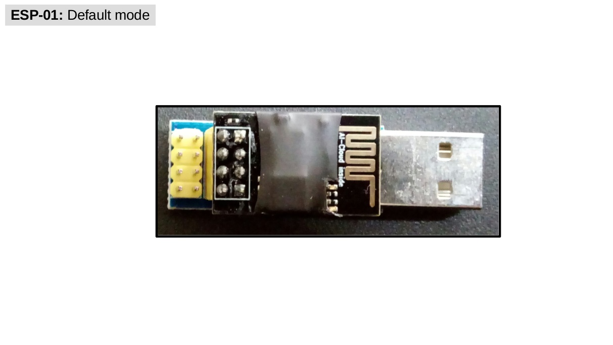
When done, disconnect the adapter from your computer and put it back into default mode by removing the jumper grounding
IO0, as follows: -
Reconnect your ESP-01 adapter and scan the nearby WiFi networks. If correctly flashed, you should be able to see a new
tasmota_*WiFi network created by your ESP-01 WiFi module; if this is not the case, then double check all steps, use a different wire to groundIO0, and try again. (If the problem persists, it might be hardware-related. Try a different adapter or ESP-01 or both.)
If you reached this part, it means your ESP-01 is already running Tasmota (Hurrah!). In the next section, we will learn how to configure the Tasmota firmware over-the-air.
Basic Tasmota configuration
In this section, we will learn how to connect the ESP-01 to a local wireless network, set a default Template for the device, fix its time, and configure its MQTT client.
Initial WiFi configuration
After a fresh installation (or power cycling your device seven times in a short period), the Tasmota firmware automatically creates a wireless access point (WAP) that other devices can connect to. The WAP is called tasmota_*, in which * will be a combination of the device’s MAC address and random numbers. To configure the WiFi in your new Tasmota device, do as follows:
-
Make sure the ESP-01 is powered on in default mode.
-
Use a wifi-capable device (e.g., laptop) and connect to the WAP named
tasmota_*. -
The ESP-01 will give your device an IP address, which you can check via
ip a. Usually, the device’s IP address is in the192.168.4.0/24pool, which means the Tasmota web UI is athttp://192.168.4.1:80; Otherwise, the web UI will be at the first address in whichever pool your device connected to after joining the WAP created by the Tasmota firmware. -
Open a web-browser of your choice (e.g., Mozilla Firefox) and navigate to the Tasmota web UI. You should be prompted to change the WiFi settings to allow your ESP-01 to connect to your local WiFi network. Change the settings, save it, and wait for the ESP-01 to reboot.
-
Navigate to the DHCP server of your local network and find the IP address assigned to your ESP-01. At this point, it’s a good idea to assign a static address to it as well. (If you set a static address, then reboot the ESP-01 before moving on.)
-
Navigate to the Tasmota web UI on your local network to set the additional configurations described in the next section.
ESP-01 Template
Tasmota templates are device-specific definitions of how their GPIO pins are assigned and therefore, proper configuration of the template is key if you plan on using the device’s GPIO pins. As you will notice, the default template in the tasmota-sensors.bin binary is for the Sonoff Basic device, which won’t work for us. The actual template for the ESP-01 can be found at https://templates.blakadder.com/ESP-01S.html. To change the current Sonoff template to the proper ESP-01 template, do the following:
-
Copy the ESP-01 template:
{"NAME":"ESP01","GPIO":[255,255,255,255,0,0,0,0,0,0,0,0,0],"FLAG":0,"BASE":18} -
From the Tasmota web UI, go to Configuration > Configure Other.
-
Paste the template under Other parameters > Template. Then, check the Activate option under the template. Save the settings and wait for the reboot.
-
The device should now be named ESP01 (or whatever
NAMEwas in the template). If everything looks good, go to the next section.
Timezone
If you installed a pre-compilled firmware, there is a chance your device is using the incorrect timezone. To check the current timezone, go to Console and type:
timezone
If the timezone does not match yours, you can enter the timezone command with a value equal to your region’s standardized time zone. For America/Sao_Paulo, for example, that would be -3, which can be set in your Tasmota device as follows:
timezone -3
Now if you enter time in the console, it should correctly display your current local time.
MQTT
It is possible to interact with a Tasmota device in multiple ways (e.g., HTTP requests, web UI console, serial) but MQTT offers a reliable and widely supported messaging protocol for managing this and many other devices using a single server/broker. If you are new to MQTT, the HiveMQ wrote a series of articles about the MQTT basics, its main features and other related resources that I invite everyone to read:
There are many options when it comes to MQTT software. Here, I will show how to install and configure the Eclipse Mosquitto MQTT broker on a Docker container. The MQTT broker will be configured to use client authentication (username and password) on the default listener port (1883) and persist its config, data, and log directories.
MQTT broker configuration
If you already have a running MQTT broker instance, skip to the next section to configure the Tasmota MQTT client; Otherwise, to install and configure the Mosquitto MQTT broker in a Docker container, follow these steps:
- Install Docker Engine on your OS. Here’s a quick reference to two popular Linux distributions:
Optional. Afterwards, install Portainer - Community Edition to manage your Docker containers.
-
Create a local directory in
/optof your host machine to store permanently the contents of the Mosquittoconfig,data, andlogcontainer directories:cd /opt sudo mkdir mosquitto mosquitto/config mosquitto/data mosquitto/log -
Create an empty
pwd.txtpasswords file in the newly createdconfigdir:sudo touch /opt/mosquitto/config/pwd.txt -
Create and edit a
mosquitto.confconfiguration file for the MQTT broker in the same dir:sudo -e /opt/mosquitto/config/mosquitto.confand paste the following, which disables anonymous access, enables user credentials by pointing
password_fileto thepwd.txtfile, and sets a custom location for themosquito.dbandmosquito.logfiles:per_listener_settings true allow_anonymous false listener 1883 persistence true persistence_location /mosquitto/data log_dest file /mosquitto/log/mosquitto.log password_file /mosquitto/config/pwd.txt -
Now we are ready to install the MQTT broker container. Pull the official Eclipse Mosquitto broker Docker container:
docker pull eclipse-mosquittoThen, run it in detached mode (
-d) with the namemosquittoand the option to always restart unless stopped (other options are to map ports and volumes between host and container, per the structure of the local directories and files we created):docker run -d \ --name mosquitto \ --restart=unless-stopped \ -p 1883:1883 \ -v /opt/mosquitto/config:/mosquitto/config \ -v /opt/mosquitto/data:/mosquitto/data \ -v /opt/mosquitto/log:/mosquitto/log \ eclipse-mosquittoIf you run into permission issues while running Docker with your current user, make sure to add your user (
${USER}) to thedockergroup (sudo usermod -aG docker ${USER}). Then, log out and back in to try again. Alternatively, appendsudoto thedockercommand. You can find this and other post-installation steps in the official Post-installation steps for Linux.Before moving on, make sure the container is running:
docker psAnd the log files are not showing any error messages:
docker logs mosquitto -
If the container is running without any issues, then let’s start a shell inside the container to edit the
pwd.txtpassword file using themosquitto_passwdutility:docker exec -it mosquitto /bin/shAnd now we will create (a) a
tasmotauser with passwordpassword123and (b) ahassuser with password123password:mosquitto_passwd -b /mosquitto/config/pwd.txt tasmota "password123" mosquitto_passwd -b /mosquitto/config/pwd.txt hass "123password"Of course, feel free to use whichever username and password you feel appropriate for your use-case. Keep in mind that unless you configure your broker and client to use encryption, these credentials are communicated in plain text over the network, which is fine if only running it locally.
When done, exit the shell inside the
mosquittocontainer:exit -
Restart the
mosquittocontainer to enable the new user credentials:docker restart mosquittoAnd we are done with the MQTT broker installation and configuration!
For information about additional options, such as setting up access control to restrict user access to specific topics, check the official Mosquitto documentation.
Tasmota MQTT client configuration
With an up and running MQTT broker, you can configure the Tasmota MQTT client as follows:
-
From the Tasmota web UI, go to Configuration > Configure Other.
-
Make sure the MQTT enable box is checked; otherwise, check and save it.
-
Now go to Configuration > Configure MQTT and configure your Tasmota device to use your MQTT broker. The specifics of these settings will depend on how your MQTT broker was configured. If you followed the instructions in the previous section, then your Tasmota MQTT client settings should look similar to the following (but change the host
192.168.10.30address to the one running your MQTT broker):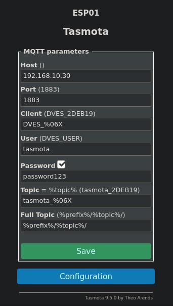
-
Hit save when done and wait for the device to reboot. If successfully configured, the Console in the web UI should show something like the following:
... MQT: Attempting connection...
... MQT: Connected
... MQT: tele/tasmota_2DEB19/LWT = Online (retained)
... MQT: tele/tasmota_2DEB19/INFO1 = {"Info1":{"Module":"ESP01","Version":"9.5.0(sensors)","FallbackTopic":"cmnd/DVES_2DEB19_fb/","GroupTopic":"cmnd/tasmotas/"}}
And if you followed the instructions in the previous section, you can also check the
/opt/mosquitto/log/mosquitto.logfile, which should show something like the following:...: New connection from 192.168.10.103:57321 on port 1883. ...: New client connected from 192.168.10.103:57321 as DVES_2DEB19 (p2, c1, k30, u'tasmota').
You can find more information about the MQTT configuration at the official Tasmota MQTT documentation.
Wiring the GY-BME280 sensor module
The GY-BME280 module usually comes with four male pin headers that we will connect do the ESP-01 USB adapter using four female-to-female jumper wires. To make use of such module, follow these steps:
-
Use your soldering kit to solder the headers to the board. If you have a multimeter, remember to test your connections afterwards.
-
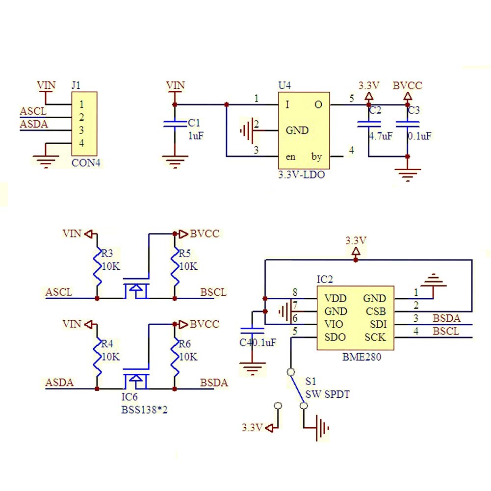
Grab four female-to-female DuPont wires and connect them to your GY-BME280 module and ESP-01 USB adapter according to the following wiring schematics:
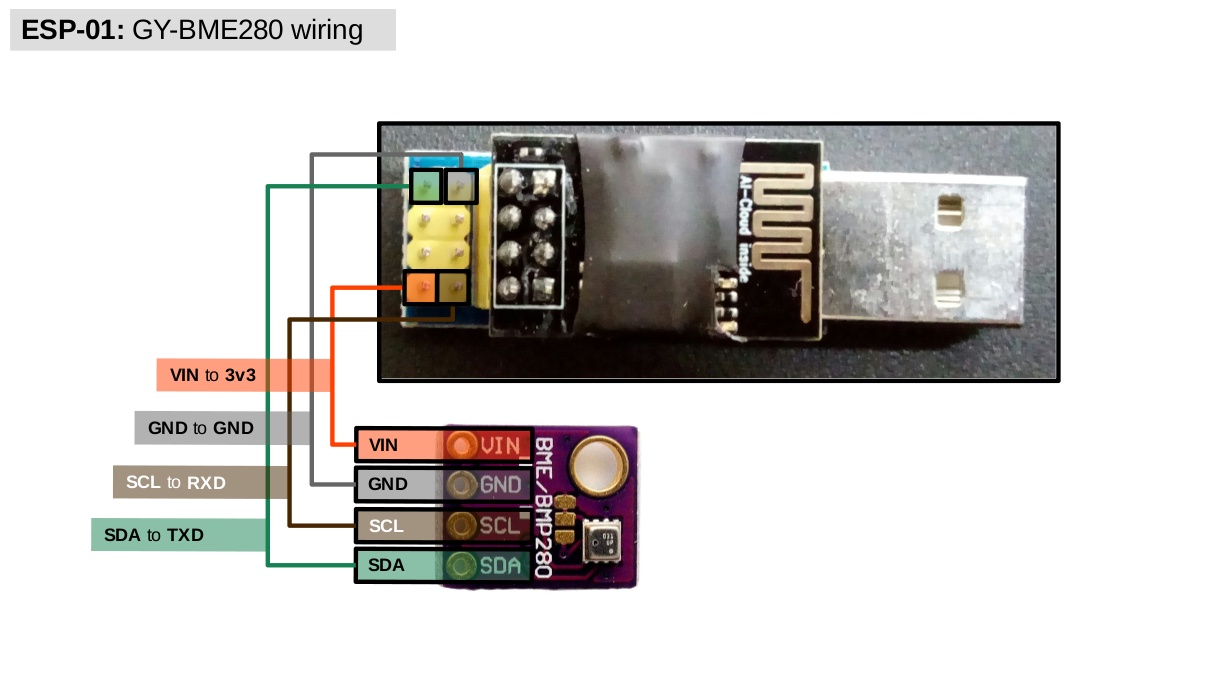
In this schematics, we will be using pins
TXDandRXDto interface with the GY-BME280 module. You could, of course, try one or two of the other GPIO pins–namely,IO0andIO2. However, because the state (low/float/high) of the latter pins at boot can put the board into specific modes of operation (e.g., whenIO0ishighat boot, the ESP-01 enters flash mode) and we will only use the USB port for power, I find it safer to use the serialTXDandRXDpins to interface with (I2C) devices when using the ESP-01. -
(Optional.) If you bought
1x4and2x4female connectors, replace the single connectors by the new ones. (If you are uncertain how to do that, check Adreas Spiess’ video on tricks for working with DuPont wires, at the 3:15 mark.) At the very least, use a tape to secure the connectors that are next to each other. This makes it harder for them to disconnect by accident. -
Once the GY-BME280 module is wired to the ESP-01 USB adapter, connect your adapter to a USB power supply and wait for it to connect to your network. (Of course, make sure it is within reach of a WAP.)
-
Now we will configure the device’s Template to use the
RXDandTXDasSCL(serial clock line) andSDA(serial data line), respectively. So, navigate to your device’s web UI and go to Configuration > Configure Template. Then, at GPIO3 (RXD), set it toI2C SCL; and at GPIO1 (TXD), set it toI2C SDA. At the end, your Template should look like the following one: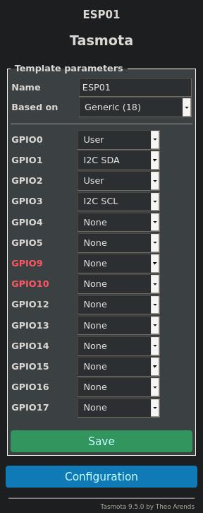
Hit Save and wait for the device to reboot.
-
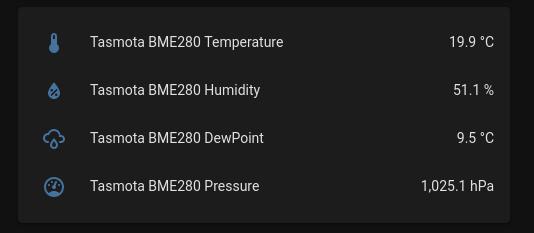
If properly configured, your device’s main web UI should now show four metrics from the BME280 sensor, namely temperature, humidity, dew point, and pressure, as in the following example:
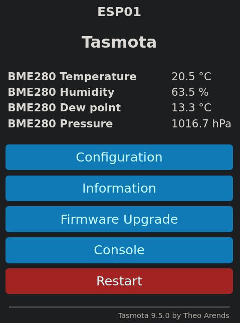
That is it! Enjoy your new IoT environmental sensor. If you need assistance setting up the integration with Home Assistant, take a look at the next section (there’s also a reference for other home automation systems). Otherwise, skip to the Conclusion for the final remarks about this project.
Home Assistant integration
The easiest way to integrate Tasmota devices to Home Assistant is via the official Tasmota integration. To make use of such integration, follow these steps:
-
Go to the Home Assistant web UI, then navigate to Configuration > Integrations > Add integration. This will open a new window with a search box. Type
mqttand select the integration. -
Configure the MQTT integration to make use of your MQTT broker. If you followed the MQTT broker configuration guide, then use the username
hasswith password123passwordto authenticate your Home Assistant in the MQTT broker. If configured correctly, you should see the MQTT integration listed in the Integrations tab of your Home Assistant Configuration window. -
Now, navigate once again to Configuration > Integrations > Add integration and search for
tasmotaand select the integration. -
Leave the discovery prefix to the default topic (
tasmota/discovery) and hit submit to enable to Tasmota integration. If configured correctly, you should see your ESP01 listed in the next window and optionally, you can select an Area that it belongs to.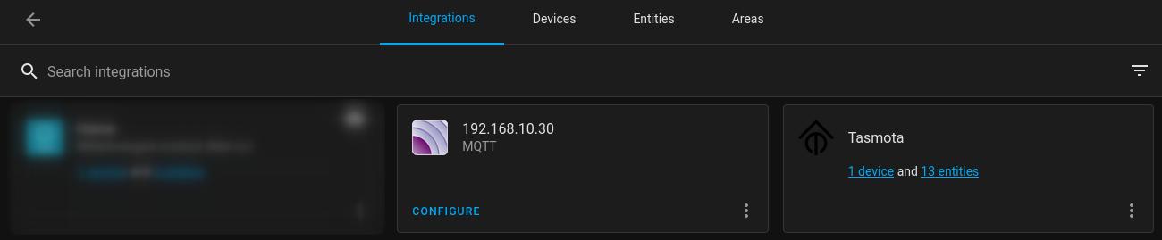
-
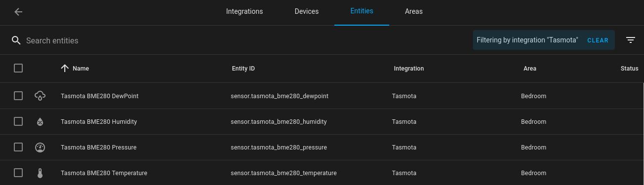
That is it! Home Assistant should now be able to automatically detect and create entities for all your BME280 environmental metrics from the current device as well as any new ones.
Of note, the use of the SetOption19 (MQTT discovery) in Tasmota devices is currently deprecated. For this reason, it is disabled by default in the latest firmware (setoption19 0) and therefore, I won’t mention its use here.
For this and other options to integrate your Tasmota device to Home Assistant or other home automation systems, check the Integrations in the Tasmota documentation.
Conclusion
In this article, we learned how to integrate the small and cheap ESP-01 WiFi module with the reliable BME280 sensor to create a USB powered and low-profile Tasmota environmental sensor. Its BME280 sensor can be used to provide accurate measures of temperature, humidity, and pressure in different parts of the household, which can all be monitored via a home automation system of choice, such as Home Assistant.
The project requires very little soldering and can be assembled in a matter of minutes and for these reasons, it’s a very good project for anyone who wants to get started on making their own IoT devices. As usual, check the Changelog for updates and if you ever get stuck on something or just want to share a few ideas and opinions, feel free to get in touch with me.