Changelog
Oct 24th, 2022: I updated portions of this guide to reflect that recent versions of the tasmota factory firmware do not require flashing a separate boot, bootloader, and partitions binaries. There is now a single binary called tasmota32-webcam.factory.bin that we use to flash the tasmota firmware onto the ESP3-cam module. Everything else should work just like before though. (If you find you’re having issues with the procedure outlined here, please refer to the official flashing instructions.) Thanks to Toz for the heads up!
Jul 6th, 2022: Tasmota version 12.02 has been recently released and it introduces a few additional features relative to its previous iterations. Most notably, the previous issue with the stable firmware version (see changelog from Feb 11th, 2022) has been fixed in the current stable. In addition, a pull request by @philrich added support to several OV2640 features that were not contemplated in the previous firmware versions. More specifically, version 12.02 includes commands for SpecialEffect, White Balance, Exposure Control, Gain Control, White/Black Pixel Correct, DCW, Gamma Correction, Lens Correction, Nightmode, and Reduced FPS mode. These new commands were all added to the table of additional webcam commands. Thanks to Eric for letting me know about these changes.
May 5th, 2022: I decided to add a new sub-section called Backup to remind everyone that Tasmota has a very useful configuration backup system that allows users to restore all settings in case something goes terribly wrong with the device. It only takes a few clicks and will save you a lot of time, so don’t skip it!
Feb 11th, 2022: It seems that the version of the tasmota32-webcam.bin firmware that contains the bug fix I referred to on December 13th has not made its way to the latest stable release yet and is actually only available in the development release binaries instead. For this reason, I suggest to download and install the development binary when following the instructions in the section Flashing Tasmota32 webcam server. Thanks to Hans for letting me know about this issue.
Dec 22nd, 2021: Included more information about power supply to the Standalone wiring section and appended one more relevant SetOption to the SetOption configurations section, namely S065, which controls the fast power cycle detection. I also wrote a note to the Wiring and template configuration subsection of Customizing the tasmota32-webcam firmware to mention that the referred GPIO pins are currently assigned to SPI-related components but can be safely freed up to be used with peripherals instead.
Dec 13th, 2021: The tasmota32-webcam.bin version 10.1.0.1 seems to have fixed the issue mentioned before. Therefore, I’m also reverting the AITHINKER CAM template back to the original, in which GPIO4 is assigned the PWM component (416).
Dec 10th, 2021: I made changes to multiple sections to reflect that the use of an independent power supply is now required after flashing the firmware. In addition, there is now a new section called Serial Console in which I described how to use screen to establish a wired connection with the board to monitor its state and help troubleshooting possible issues with it. I also added a few comments about mounting the board at the end of the Hardware section. Lastly, I should point out that there is an ongoing issue with the firmware (see next update).10.x that causes the board to become unstable after initializing the camera, so you might want to stick to firmware 9.5 for a little longer. Check the current status of this issue on Github
Dec 6th, 2021: Included a new section called SetOption configurations to add information about the boot loop defaults restoration control (SetOption36). This is useful to prevent your device from losing its configurations after power outages and other events that might cause a boot loop.
Dec 5th, 2021: I made a tiny change to the default AITHINKER CAM template in the Updating the template section to disable the PWM component on the GPIO4 (flash LED). More specifically, instead of assigning 416 (PWM) to IO4 (as in the official template for such board), the current template assigns 1 (User) to it. This change was motivated by multiple boards becoming unstable when such option was implemented (e.g., turning the flash LED on would cause one or consecutive reboots). (Of note, the same issue seems to occur with the relay component and any other component that attempts to control the flash LED. My advice is to not use it at all.) Disabling the flash LED and using 2.5A power supplies solved my random reboot and connectivity issues with the firmware 10.0.
September 3rd, 2021: Included a new section called RTSP server that describes how to enable and access the video stream via the Real Time Streaming Protocol (rtsp://). Also made a few related changes to the table in Webcam server additional configurations.
September 1st, 2021, Update #3: Extended the information about the flash and red LEDs at the end of the Webcam server additional configurations section.
September 1st, 2021, Update #2: Updated the Standalone wiring section to recommend a power supply able to deliver at least 1A instead of the 400mA previously suggested. At boot and when scanning for WiFi networks, the module can use more than 400mA, which might cause it to become unreliable if the power supply is unable to deliver more than that.
September 1st, 2021, Update #1: Fixed a few typos (e.g., ESP_HOME instead of ESP_PORT) and updated the AITHINKER CAM template in Updating the template. Also, added minor notes to help troubleshooting issues when flashing the latest firmware.
August 12th, 2021, Update #3: Made minor changes to a few commands to improve readability.
August 12th, 2021, Update #2: Per a user suggestion (Tobias), the Flashing Tasmota32 webcam server section has been updated. Specifically, the baud rate in the esptool-py utility (-b) has been omitted to use the default value (115200), which seems to work fine with the ESP32-cam module and most adapters. However, if you run into issues, try the previous value when flashing the Tasmota32-webcam binaries (-b 921600).
August 12th, 2021, Update #1: There has been changes to the location of the binary files because they moved from the Tasmota repository to the new Tasmota-firmware repository, which currently has a single branch (main). The location of the necessary binaries to flash the Tasmota32-webcam firmware via the esptool.py utility was changed accordingly in the Flashing Tasmota32 webcam server section. (It seems that changes are still being made to the organization of such files, so if the URLs do not work, check the new repo directly.)
July 16th, 2021: Updated the WcResolution command in the Webcam server additional configurations section to reflect the latest support (firmware 9.5.0) for higher resolutions (11, 12, 13). Thanks to Eric for the heads up!
April 6th, 2021, Update #2: Created a bonus content section at the end called Firmware customization. The new section describes how to create a customized Tasmota firmware to use any supported I2C or other peripherals that are not available in the pre-compiled binary. The BME280 sensor–a cheap and very reliable ambient temperature, humidity, and pressure sensor–was used as an example but the same procedure applies for displays and other I2C sensors that you might wish to use with your ESP32-cam board. This provides a very easy way to turn a simple webcam server into a weather station, smoke detector, relay controller, and more.
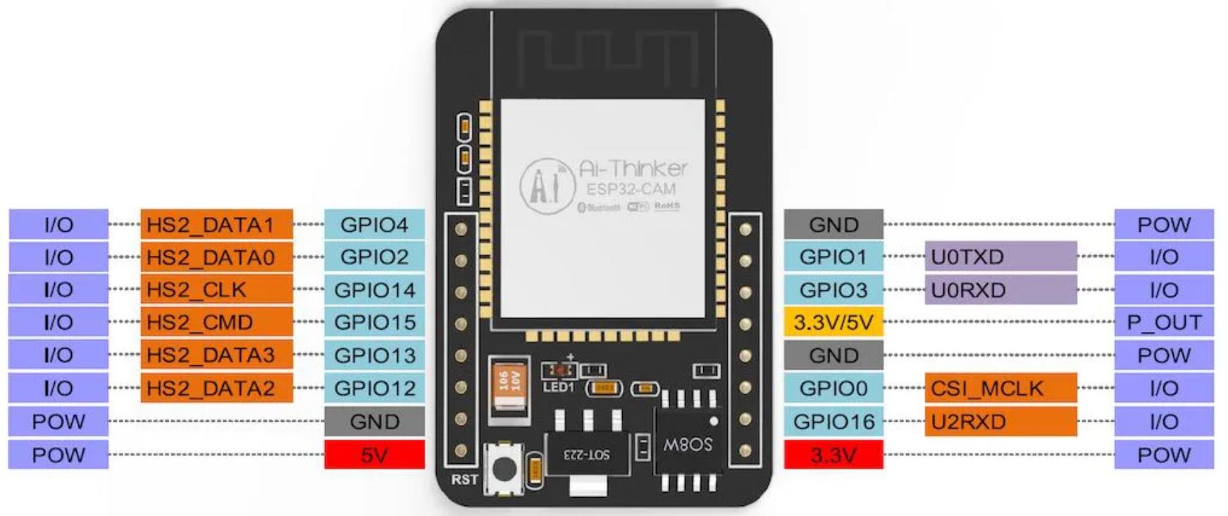
April 6th, 2021, Update #1: Added a pinout diagram for the ESP32-cam AI-Thinker board to the Hardware section.
Jan 26th, 2021: Added an alternative source for the Tasmota32 binaries to the Flashing Tasmota32 webcam server section. I few individuals reported issues flashing the latest (firmware branch) binaries, so I added a reference to the more stable (release-firmware branch) binaries instead. A list of currently active branches can be found in the official Github repo’s active branches website.
Jan 16th, 2021: Publication of the original article
Introduction
The ESP32 is a cheap and low-power microcontroller developed by Espressif. In addition to its low-cost, the ESP32 is known for its tiny and robust design, the versatility of its applications, and for having onboard Wi-Fi and Bluetooth. It is sold world-wide (e.g., Amazon, Aliexpress, Mercado Livre) in a variety of boards (e.g., NodeMCU, TTGO, Lolin32).
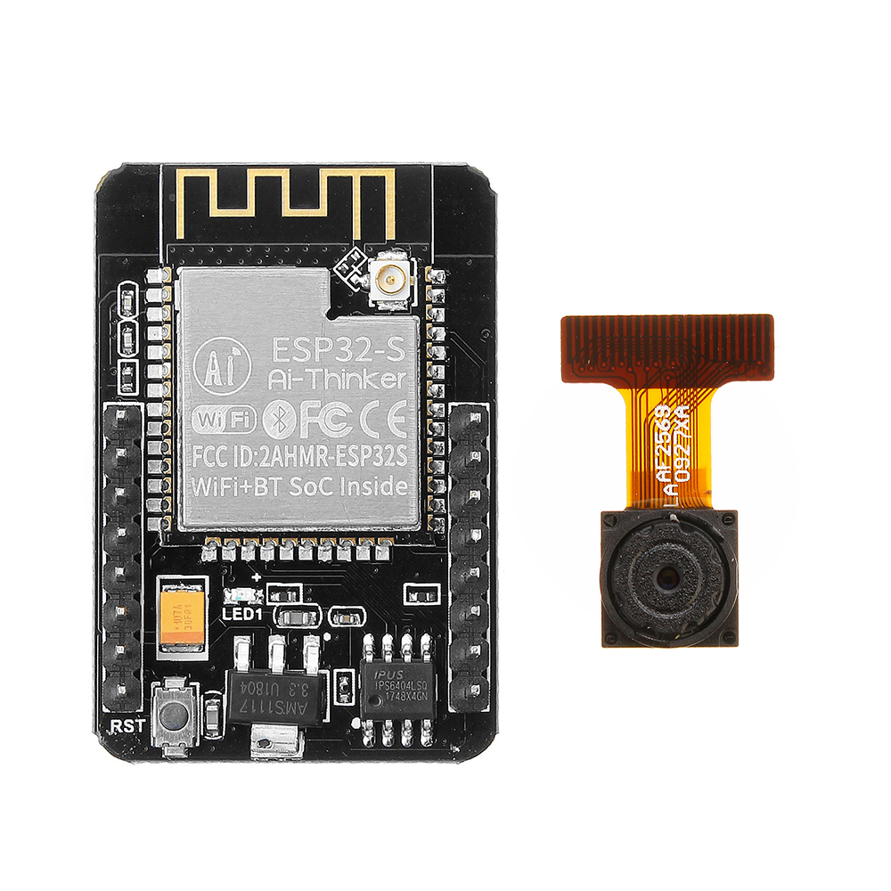
In this tutorial, I will talk about one type of ESP32 board that has an integrated camera module, called the ESP32-cam, which can be found for less than US$10. The goal is to build a cheap alternative to commercial wireless cameras using an open-source firmware that can be easily controlled via HTTP or MQTT and integrated to an existing camera surveillance server (e.g., MotionEye, Shinobi, ZoneMinder, iSpy) or multi-purpose automation server (e.g., HomeAssistant, OpenHAB, NodeRed) by capturing its live stream from a simple MJPEG URL. All that can be accomplished with Tasmota and its (beta) webcam server firmware for the ESP32-cam.
If you’re new to ESP32 boards, check Bill’s (DroneBot Workshop) review video:
For a comparison of a few different ESP32-cam boards, check Andreas Spiess’ video:
Overview
This tutorial was organized as follows. First, I presented the motivation behind the use of Tasmota32 webcam server over one of the most common firmwares for the ESP32-cam, the Espressif CameraWebServer Arduino sketch. This is followed by a list of the main hardware components involved into flashing a firmware onto the ESP32-cam. Most of the tutorial focused on the installation and configuration of the Tasmota32 webcam server using a GNU/Linux OS.
Why Tasmota?
Tasmota was created and it is still maintanted by Theo Arends. It started as hacky alternative to the Sonoff commercial firmware and moved onto an independent, free and open-source project that provides multiple firmwares for ESP8266-based devices. The firmwares come with a simple webUI that let’s you control and configure the board main modules as well as integration with a MQTT server and more. Even though Tasmota support for the ESP32 is still in beta development, my experience with it has been very positive.
One of the main webcam firmwares for the ESP32-cam is the one provided by Espressif themselves, the CameraWebServer Arduino sketch. This one has features that the Tasmota32 webcam firmware does not offer, such as face recognition and motion detection. However, my experience with the video streaming has been negative. Specifically, the streaming runs smoothly when the video resolution is low (640x480) but it strugles quite a bit when running at medium to high resolutions–that is, the number of frames per second decreases noticeably. I’ve also noticed that the board runs very hot when running the CameraWebServer Arduino sketch, even when the most CPU intensive tasks (motion detection and face reconition) are disabled.
On the other hand, the Tasmota32 webcam server seems to perform much better in the areas the CameraWebServer Arduino sketch strugles with. More specifically, the streaming is smoother and the board does not seem to get as hot. I’ve not had a chance to investigate why this happens and to measure the actual difference in frames per second and temperature, so don’t take my opinion too seriously. Also, I cannot tell if this happens for all ESP32-cam boards because I’ve only tested with the AI-Thinker module. Overall, however, my experience with the Tasmota32 firmware has been better than with the Espressif firmware in the area that I think is the most relevant one for a camera module, namely video streaming performance. On top of that, the Tasmota firmware offers a multitude of methods to interact with the ESP32-cam remotely, while the Espressif sketch is very limited in that regard.
If you’ve never heard of Tasmota before, check Robbert’s (The Hook Up) introduction video:
Hardware
To make a single wireless camera based on the ESP32-cam board, you’ll need at least the following items:
- Board:
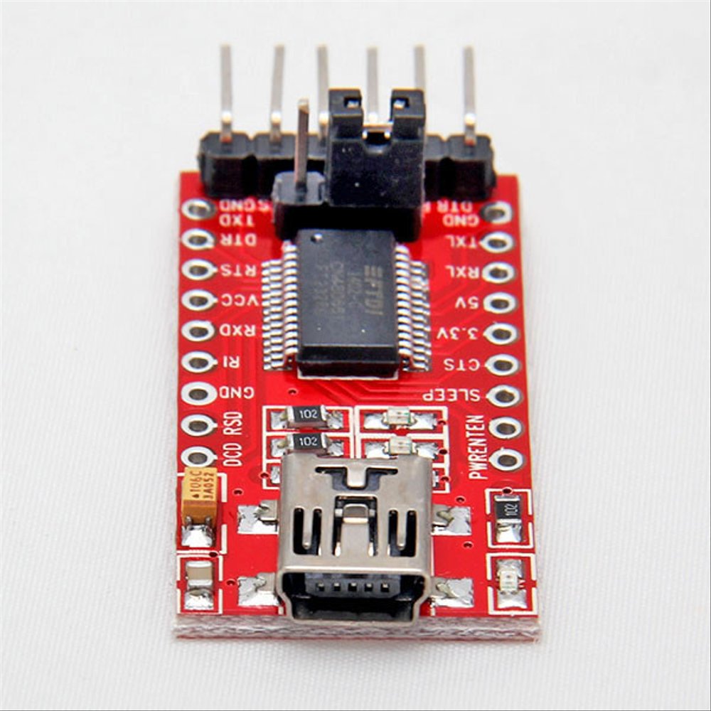
- USB to TTL adapter: Used to interface with the board when connected to a computer. It can only provide power to the board during the initial flashing stage.
- Cables: Long and thin cables can add significant resistance, so at the very least, try to keep them short.
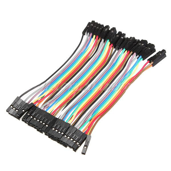
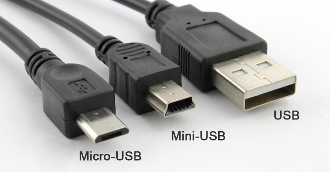
- 01x USB cable compatible with your USB to TTL adapter: Check the USB type and use a short cable to decrease resistance as much as possible because initially, we will be powering the ESP32-cam via your computer’s USB port.
-
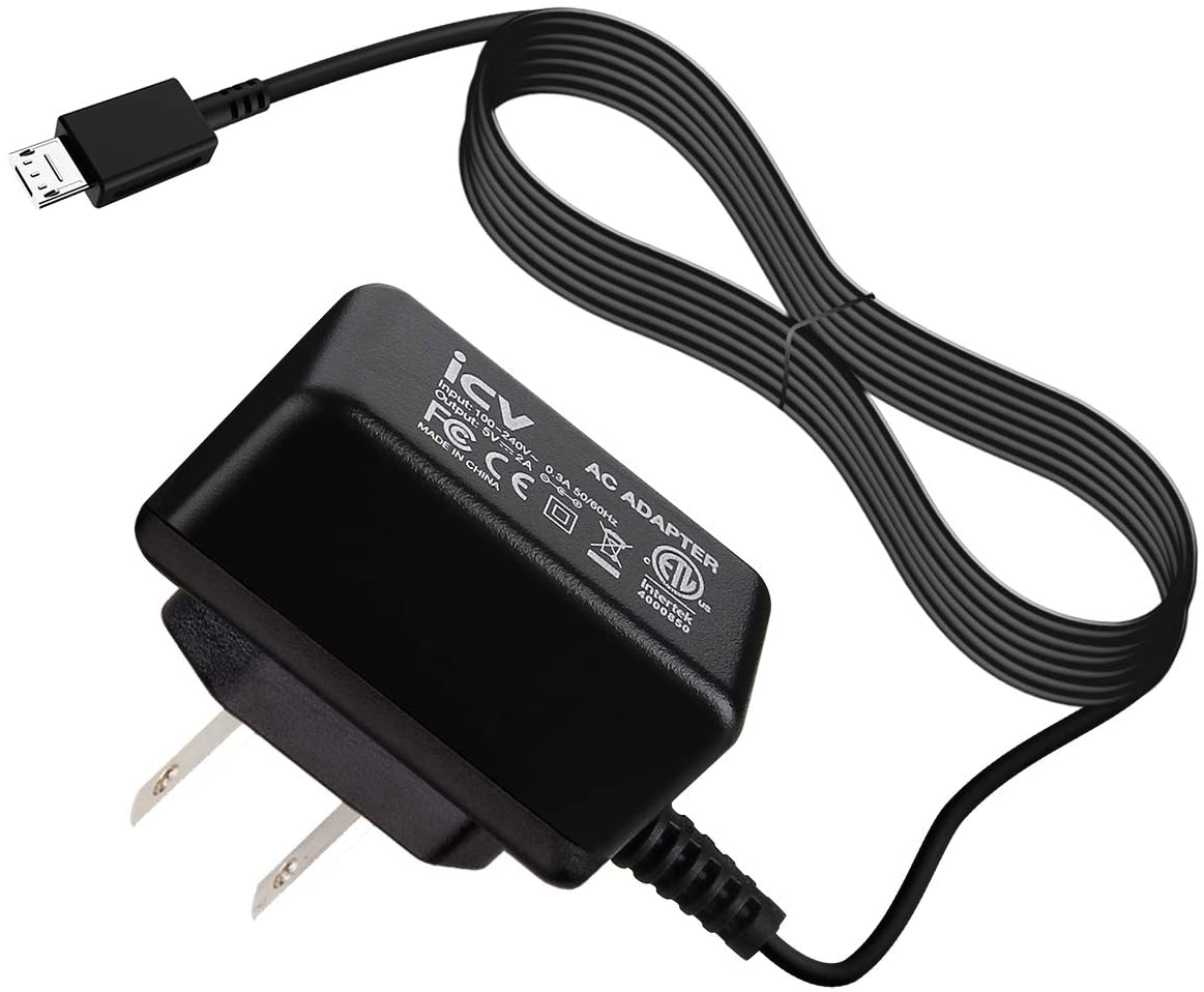
Power supply: Once you are done flashing the Tasmota firmware, you will need to power the board independently because your computer’s USB port and your TTL adapter won’t be able to deliver enough current at a reliable 5V to run the board with the new firmware. (See the Standalone wiring section for more information on how to properly power your ESP32-cam project.)
-
01x AC to 5V DC (2A) power supply: If you have an old 5V charger lying around (e.g., from an old cellphone or tablet), you might be able to use it as well but make sure it is able to deliver at least 1A. However, if you run into power-related issues, consider buying a new power supply able to deliver at least 2A instead.
-
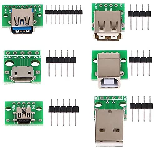
01x USB to DIP adapter: Make sure to buy at least one DIP adapter that is compatible with your power supply. (In our case, only the VCC and GND pins need to be soldered.) It doesn’t need to be a USB adapter if your power supply has a barrel connector, for example, in which case a simple DC 2.1x5.5mm adapter will be enough.
-
-
Casing: Casing is not covered in this tutorial, owing to the plethora of alternatives. If you wish to add a case to your ESP32-cam project, there are many 3D printed options to choose from. You can also use pretty much any small prototyping box, fake camera case, etc., as long as it is capable of housing the module.
However, notice that the module does not have screw holes for securing it to a flat surface. In such cases, my preferred alternative is to solder a few of the exposed pins to a mini solderable breadboard and then secure the breadboard with metal/nylon screws to the casing. This gives the project a more clean and professional look than using hot glue, for instance. In addition, having a breadboard makes it easy to attach additional components to your project (e.g., BME280 sensor).
Installation
This guide assumes you’re running a Linux distribution, and more specifically, an apt-based distro, such as Debian or Ubuntu. If you’re running a different distro, simply change the apt code to reflect your system’s package manager. For non-Linux users, check Tasmota’s Getting Started but use the binaries mentioned here and come back for the post-flashing configuration of the webcam server.
Required packages and user permissions
Before we can flash the Tasmota32 webcam server onto the ESP32-cam, we will need to install a few packages and configure the permissions of our Linux user.
-
Open a terminal and install the required packages:
sudo apt update sudo apt install wget python3 python3-pip -
Install
esptool.pyviapip3:pip3 install esptool -
Find out if
esptool.pycan be found in your user’s$PATH.whereis esptool.pyAlternatively, when required to run
esptool.py, instead ofesptool.py OPTIONS, run aspython3 -m esptool OPTIONS. If you choose to do this, skip the next step. -
If
esptool.pywas not found, it means your user’s.local/binis not in your$PATH. Add it as follows:echo "export PATH="$HOME/.local/bin:$PATH"" | tee -a "$HOME/.bashrc" > /dev/null -
Connect your ESP32-cam to the USB to TTL/serial adapter in flash mode:
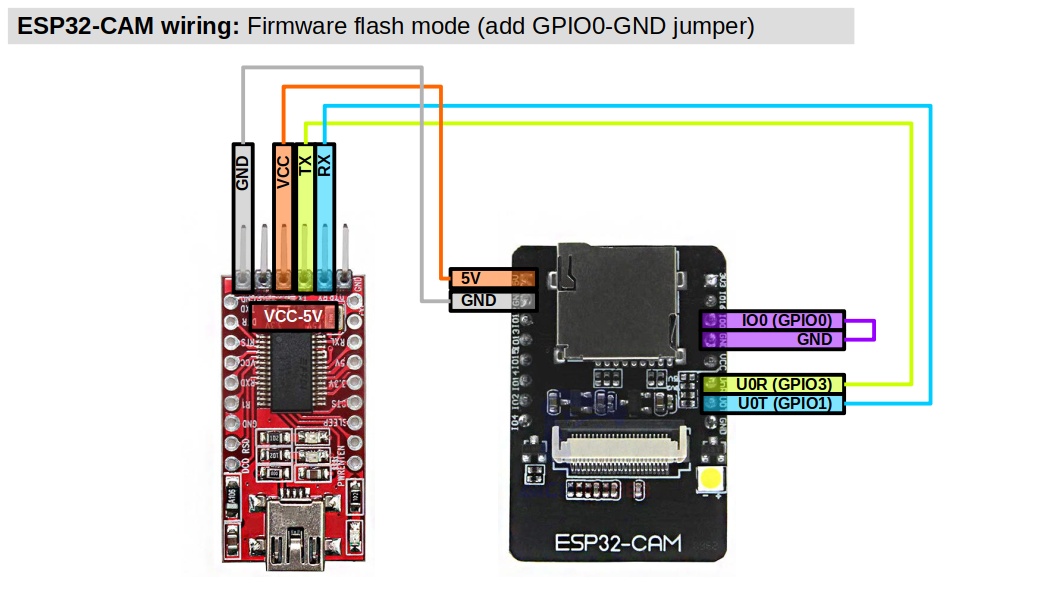
Attention. Make sure your USB to TTL adapter has VCC in 5V mode and in the ESP32, the VCC cable is connected to the 5V pin. Double check the wiring before moving on.
-
Connect the adapter to a USB port on your computer and check the new device in
/dev/:ls -l /dev/ttyUSB* -
Add your
$USERto the same group as/dev/ttyUSB*(it’s usuallydialoutbut if different, change in the command below) andtty:sudo usermod -aG dialout,tty ${USER} -
Log off and back on. (If you continue to run into permission issues, try rebooting instead. You can check your user’s permissions with
id ${USER}.)
Flashing Tasmota32 webcam server
We are now ready to flash the Tasmota firmware. For reference, the official information is available at https://tasmota.github.io/docs/ESP32.
-
Create a
tasmota32dir in/opt:cd /opt sudo mkdir tasmota32 -
Change ownership of the new directory to the current user instead of
root:sudo chown ${USER}:${USER} tasmota32/ -
Download the
tasmota32-webcam.factoryb.bi.factorynbinary and the needed ESP32 Tasmota binaries from the official Github repo viawget. (The following was updated on August 12th, 2021.) The binaries are now available in a different repository than before, namely arendst/Tasmota-firmware, and currently, the new repository has a single branch (main). There are two versions of thetasmota32-webcam.factory.bin, one from thereleaseand another from thedevelopmentportions of the Tasmota32 project. My advice is to try the stable release first, then development if you have any issues, unless there is a note in Changelog that says otherwise (e.g., theFeb 11th, 2022note).To download the stable release binary, use the following command:
wget -P /opt/tasmota32/ https://ota.tasmota.com/tasmota32/release/tasmota32-webcam.factory.binAlternatively, to download the development binary, use the following command:
wget -P /opt/tasmota32/ https://ota.tasmota.com/tasmota32/tasmota32-webcam.factory.bin -
Make sure your ESP32-cam is connected to your computer in flash mode (GPIO0-GND jumper). Now find the USB port your device is using in
/dev/and set it to the environmental variableESP_PORT, as follows:Attention. While convenient, the following command assumes there is a single USB to serial adapter connected to your computer. If this is not the case, manually set
ESP_PORTto whichever port your USB adapter is currently using. You can find the port vials /dev/ttyUSB*and testing one by one until you find the one used by the adapter. Alternatively, simply disconnect all other USB to serial adapters for this procedure and continue.ESP_PORT=$(ls /dev/ttyUSB*)Please notice that this only works if you continue to use the same shell in which
ESP_PORTwas defined. If you log off or even close the current terminal, you will have to redefineESP_PORTto keep using it.You can check that
ESP_PORTwas correctly defined byechoing it, as follows:echo $ESP_PORTwhich should output something like this:
/dev/ttyUSB0 -
Erase the current firmware (or whatever data) from your ESP32-cam.
Attention. The following procedure will wipe all the data on the ESP32-cam.
esptool.py --port $ESP_PORT erase_flashWait until
esptool.pyis done. Then, press the reset button on the ESP32-cam. Now, check that$ESP_PORTis available again. -
Flash the
tasmota32-webcam.factory.binwebcam server binary and the required Tasmota binaries to the ESP32-cam.esptool.py --chip esp32 \ --port $ESP_PORT \ --before default_reset \ --after hard_reset \ write_flash -z \ --flash_mode dout \ --flash_size detect \ 0x0 /opt/tasmota32/tasmota32-webcam.factory.binWait until
esptool.pyis completely done before moving on. Flashing a firmware can take a few minutes to complete. If you experience issues while flashing, try a different baud rate (-b) than the default115200, such as-b 921600. The Tasmota FAQ can help with this and other issues.If
esptool.pyhangs atConnecting..., then press the Restart button (RST) on your ESP-cam module. -
Wait until
esptool.pyis done. Then, disconnect your USB to TTL adapter from your computer and remove the flash mode (GPIO0-GND) jumper from the ESP32-cam.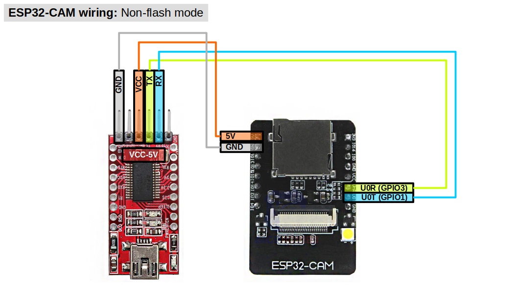
You are now ready to power your new Tasmota ESP32-cam device using an independent power supply. In the following sections, we will see how to monitor the device via the TTL adapter, which is optional, and then how to power the device and configure it, which are both required.
Serial Console
This section is optional but strongly recommended to facilitate troubleshooting power issues, incorrect component specification, random reboots, and so on. Feel free to skip to Standalone Wiring if you do not feel like setting up a serial connection to monitor your board while you configure it.
Setting up a serial connection to your Tasmota ESP32-cam device allows you to monitor its state via a wired connection to your computer. This is useful to troubleshoot issues that occur before you can access the device’s web interface (e.g., unable to connect to its access point, boot loops) and during the initial configuration steps because there won’t be any physical markers of the device’s state to rely on.
To create a serial console for your device, you’ll need a (a) USB to TTL adapter and a (b) terminal emulator. If you followed this guide, you should already have a USB to TTL adapter, which should now be connected to the ESP32-cam board as follows:

To establish a serial monitor, we will use a GNU application called screen. First, open a terminal and check whether it is installed on your computer or not:
which screen
and if which is unable to find the application, then install it via your systems package manager. For apt-based distros:
sudo apt update && sudo apt install screen
Now, connect your USB to TTL adapter to your computer and just like before, find the USB port your adapter is using in /dev/:
ls /dev/ttyUSB*
and if different than echo $ESP_PORT, set it to the environmental variable ESP_PORT; else, continue.
screen has many options but in this case, we just need to enter the following to establish a connection and log the output (-L) to a file called screenlog.0:
screen -L $ESP_PORT 115200
To quit screen, press Ctrl + a and then \, which will prompt screen to ask if you want to quit (y).
Of note, the command C- referred to in the manual stands for Ctrl plus another letter. You can see a list of default commands via C-a ? when running screen.
That is it! You are now all set to start configuring your device or troubleshooting any issues with it. Once you power your Tasmota ESP32-cam device, it should start outputting messages to your computer via screen.
Standalone wiring
If you bought a USB to DIP adapter, you can now power your ESP32-cam independently, as follows:
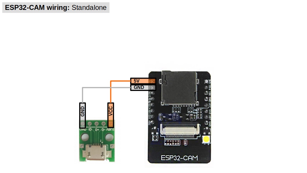
Use a 5V power supply that is able to deliver at least 1A, such as an old cellphone charger. However, if you start running into power-related issues (e.g., Brownout detector was triggered), replace your power supply for one able to deliver at least 2A instead and check that your cable is rated for such current.
During boot and when searching for wireless access points, the board requires far more power than when idling. Because a few power supplies were not designed to handle such sudden changes in energy consumption, voltage drops and insufficient current to the board might happen, which cause the device to become unstable and trigger a reboot.
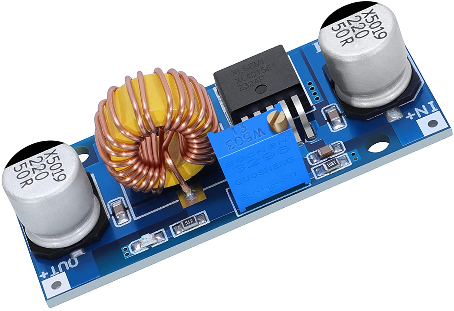
If brownout issues persist after changing your power supply, my recommendation is to make use of a buck converter in between your power supply and the ESP32-cam board. The addition of a buck converter gives you more flexibility in choosing a power supply, the ability to adjust the output voltage to better fit your project, additional output current, short-circuit protection, and built-in voltage smoothing/filtering. For reference, I have used various converters based on the cheap LM2596 in ESP32-cam projects with great success. You can easily buy one of such converters for less than US$2 and if you do not have a multimeter, some even come with an LED display to show the input and output voltage. However, depending on your needs, there are other (slightly more expensive but slightly better, too) buck converters out there that you can use as well. In any case, make sure to regulate your converters before attaching to your board; else, it might permanently damage your board and components.
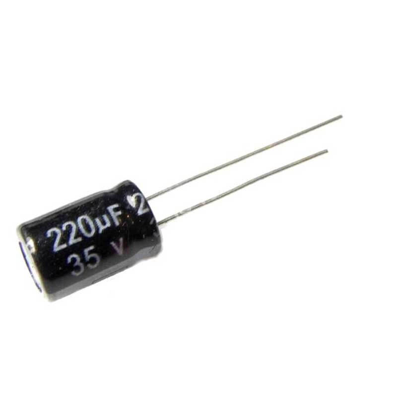
If you do not want to buy or don’t have space to add a buck converter to your project, another possible solution to brownout issues include the addition of an electrolytic capacitor across the 5V and GND pins, which should be placed close to the ESP32-cam pins. Notice that this is exactly what is done in buck converters for the purpose of handling voltage instability, and quite often, a 220uF electrolytic capacitor is used for such a purpose, so you might want to use one as well (any cap rated 10V or higher should be fine). However, the inability to easily regulate the output voltage might prove to be an issue still.
Finally, if power supply instability is inherent to your project (e.g., battery or solar-power based), then take a look at the SetOption configurations section. By default, the Tasmota firmware implements multiple power related configurations that can revert one or all changes you have made to rules, templates, components, etc. (see SO36), or even reset the device completely (see SO65).
For more information about powering this and other electronics projects, you might want to take a look at the following videos made by DroneBot Workshop and Andreas Spiess:
Configuration
By default, a fresh install of the Tasmota firmware will create a wireless access point for your ESP32-cam.
If you cannot find the Tasmota wireless access point, it is possible that the USB adapter is unable to provide enough power to operate the WiFi features in a reliable way. In this case, check the Standalone wiring section.
-
Use a wifi-capable device (e.g., laptop) and connect to it. The ESP32-cam will give your device an IP address, which you can check via
ip a. Usually, the device’s IP address is in the192.168.4.0/24pool, which means the ESP32-cam webUI is at192.168.4.1:80; Otherwise, the webUI will be at the first addr in whichever pool your device connected to after joining the wireless access point created by the Tasmota firmware. -
Open a web-browser of your choice and navigate to the ESP32-cam webUI. You should be prompted to change the wifi settings to allow your ESP32-cam to connect to your local wifi network. Change the settings, save it, and wait for the ESP32-cam to reboot.
-
Navigate to the DHCP server of your local network and find the IP address assigned to your ESP32-cam. At this point, it’s a good idea to assign a static address to it as well. (If you set a static address, then reboot the ESP32-cam before moving on.)
-
Navigate to the ESP32-cam webUI on your local network and start the configuration process (see below).
Updating the template
Tasmota templates are device-specific definitions of how their GPIO pins are assigned. As mentioned before, there are multiple ESP32-cam boards out there with different definitions. In my case, I’m using the AI-Thinker cam module and therefore, I should configure the Tasmota32 webcam server to use the AITHINKER CAM template instead of the default one. (If your ESP32-cam is different, then check https://tasmota.github.io/docs/ESP32/ for the appropriate template and use that one instead of the AITHINKER CAM.)
-
Copy the AITHINKER CAM template:
{"NAME":"AITHINKER CAM","GPIO":[4992,1,672,1,416,5088,1,1,1,6720,736,704,1,1,5089,5090,0,5091,5184,5152,0,5120,5024,5056,0,0,0,0,4928,576,5094,5095,5092,0,0,5093],"FLAG":0,"BASE":2} -
From the ESP32-cam webUI, go to Configuration > Configure > Configure other.
-
Paste the template under Other parameters > Template; Check Activate; Save it and wait for the reboot.
If you lose connection to the ESP-cam afterwards, it is very likely that the AITHINKER CAM template has changed since the last time this article was updated. In this case, put the ESP-cam in flash mode and flash the Tasmota32-webcam firmware once again. Then, when updating the Template, use the one from https://tasmota.github.io/docs/ESP32/#aithinker-cam instead of the one mentioned before.
-
The device should now be named ‘AITHINKER CAM’ (or whaterver NAME was in the template).
-
The MJPEG stream should be accessible at
http://DEVICE_IP:81/streamorhttp://DEVICE_IP:81/cam.mjpeg. -
A single snapshot can be obtained at
http://DEVICE_IP:80/snapshot.jpg.
Auto-enabling the webcam server at boot
If your board is like mine, the stream does not initialize on its own at boot–it requires a request to get webUI to initialize the stream. This will happen whenever you try to visit the device’s webUI. However, if you want to automatically initialize the webserver and video stream at boot, we can do so using Tasmota’s rules. More specifically, we will add Rule1 that tells the ESP32-cam to start the stream once Tasmota is fully initialized (i.e., after wifi and MQTT are connected, if configured).
-
Copy the following rule:
Rule1 ON System#Boot DO WcInit ENDON -
Go to the ESP32-cam webUI and then Console.
-
Paste the rule in the enter command box and press enter.
-
To enable
Rule1, enter the following command:Rule1 1 -
Restart the ESP32-cam with the following command:
Restart 1 -
Once it comes back on, check the console if
RULE 1was executed. It should show something similar to the following if the rule is working as expected:... RUL: SYSTEM#BOOT performs "WcInit" ... SRC: Rule ... CMD: Group 0, Index 1, Command "WCINIT", Data "" ... CAM: Stream init ... CAM: User template ... CAM: PSRAM found ... CAM: Initialized ... RSL: stat/tasmota_***/RESULT = {"WCInit":"Done"} -
The MJPEG stream should now be accessible at
http://DEVICE_IP:81/streamorhttp://DEVICE_IP:81/cam.mjpegwithout ever accessing the webUI’s main page.
By the way, rules are a great way to program your Tasmota device indepedently of any automation server. Make sure to read about how to add or modify rules and the list of available rule commands.
RTSP server
As of release 9.5.0, it is possible to use Real Time Streaming Protocol (RTSP) to access the video streaming from the ESP32-cam module running the Tasmota32-webcam firmware. (Thanks to @gemu2015 for the initial implementation and pull request.) To do so, follow these steps:
-
Navigate to the ESP32-cam webUI and then go to the Console.
-
Enable the RTSP server by entering the following command:
WcRtsp 1 -
Now, the video stream should be accessible via RTSP using the following address:
rtsp://DEVICE_IP:8554/mjpeg/1Remember to change
DEVICE_IPfor the IP address of your ESP32-cam.
Currently, the RTSP server only needs to be enabled once. So, contrary to WcInit, we won’t need to write a new rule to re-enable it at boot. Of note, the RTSP server is independent of the HTTP one. In addition, I’ve only tested it with VLC and there are reports of compatibility issues with other players.
Webcam server additional configurations
A full list of commands for ESP32 devices can be found at the official docs page. However, several commands that are specific to the Tasmota32 webcam server binary are often not documented there. For this reason, I’ve decided to post below all the additional commands (wc) that I’m aware of.
| Command | Definition | Values |
|---|---|---|
Wc |
Displays all the current webcam settings | - |
WcStats |
Show webcam related statistics | - |
WcInit |
Initializes the HTTP webcam server | - |
WcStream |
Controls the video streaming | 0: stop, 1: start |
WcRtsp |
RTSP server | 0: disable, 1: enable (forces a restart) |
WcColorbar |
Show Colorbar | 0: no, 1: yes |
WcFeature |
Set extended Feature | 0: off |
1: Reduced FPS mode, which reduces framerate and also increases exposure time to improve low light performance. |
||
2: Nightmode, which further increases exposure time and lowers the framerate depending on available light. |
||
WCFlip |
Flips the image vertically | 1, 0 |
WCMirror |
Flips the image horizontally | 1, 0 |
WcResolution |
Image resolution | 0: FRAMESIZE 96x96 |
1: FRAMESIZE 160x120 |
||
2: FRAMESIZE 176x144 |
||
3: FRAMESIZE 240x176 |
||
4: FRAMESIZE 240x240 |
||
5: FRAMESIZE 320x240 |
||
6: FRAMESIZE 400x256 |
||
7: FRAMESIZE 480x320 |
||
8: FRAMESIZE 640x480 |
||
9: FRAMESIZE 800x600 |
||
10: FRAMESIZE 1024x768 |
||
11: FRAMESIZE 1280x720 |
||
12: FRAMESIZE 1280x1024 |
||
13: FRAMESIZE 1600x1200 |
||
WcBrightness |
Image brightness | -2, -1, 0, 1, 2 |
WcContrast |
Image contrast | -2, -1, 0, 1, 2 |
WcSaturation |
Image saturation | -2, -1, 0, 1, 2 |
WcSpecialEffect |
Set Special Picture Effect | 0: off |
1: inverted |
||
2: black and white |
||
3: red |
||
4: green |
||
5: blue |
||
6: yellow |
||
WcAWB |
Auto White Balance | 0: no, 1: yes |
WcWBMode |
White Balance Mode | 0: auto, 1: manual |
WcAWBGain |
Auto White Balance Gain | 0: no, 1: yes |
WcAEC |
Auto exposure control (Sensor) | 0: no, 1: yes |
WcAECDSP |
Auto exposure control (DSP) | 0: no, 1: yes |
WcAECValue |
Auto exposure control value | 0, …, 1024 |
WcAECLevel |
Auto exposure control level | -2, …, +2 |
WcAGC |
Auto gain control | 0: no, 1: yes |
WcAGCGain |
Auto gain control gain | 0, …, 30 |
WcGainCeiling |
Gain ceiling | 0, …, 6 |
WcGammaCorrect |
Auto Gamma Correct | 0: no, 1: yes |
WcLensCorrect |
Auto Lens Correct | 0: no, 1: yes |
WcWPC |
White Pixel Correct | 0: no, 1: yes |
WcDCW |
Downscale | 0: no, 1: yes |
WcBPC |
Black Pixel Correct | 0: no, 1: yes |
For example, to set the stream resolution to 800x600, go to the Console and enter the following command :
WcResolution 9
Alternatively, it’s possible to send commands via HTTP. The previous example via web-browser: http://DEVICE_IP/cm?cmnd=WcResolution%209. If using a terminal, you can send via curl, as follows:
curl http://DEVICE_IP/cm?cmnd=WcResolution%209
which should reply with a json parsable by utilities such as jq.
Finally, the flash LED is controlled by GPIO4 and the red LED is controlled by GPIO33. Their state can be changed programmatically as well.
Fixing the timezone
If you installed a pre-compiled firmware, there’s a chance your device is using the incorrect timezone. To check the current timezone, go to Console and type
timezone
and to change it, enter the command with a value equal to your region’s standardized time zone. For America/Sao_Paulo, for example, that would be -3, which can be set in your Tasmota device as follows
timezone -3
SetOption configurations
Tasmota has a command called SetOption<x> (or SO<x>) that allows users to change various default firmware behaviors, such as whether to preserve power state after a restart (SO0), which temperature scale to use (SO8), and so on. One such options, namely SetOption36 (SO36), is responsible for the boot loop defaults restoration control. A boot loop is defined as a restart within less than 10s before restoring settings (according to the BOOT_LOOP_TIME default value), and by default, the Tasmota firmware will start applying the following changes as soon as it detects a single boot loop (SO36 1 is the default):
- 1st restart: disable ESP8285 generic GPIOs interfering with flash SPI;
- 2nd restart: disable rules causing boot loop;
- 3rd restart: disable all rules (and autoexec.bat);
- 4th restart: reset user defined GPIOs to disable any attached peripherals;
- 5th restart: reset module to Sonoff Basic (1).
Fortunately, such option can be disabled entirely (SO36 0) or customized (e.g., start boot loop control after 5 boot loops: SO36 5). This matters because if for any reason your device detects a boot loop (e.g., bad power supply during boot), it will start reverting many of the customizations you’ve configured before (e.g., rules and template), which might cause loss of connectivity and other related issues. Personally, I like to disable boot loop control altogether once I have thoroughly tested the current configuration, which can be done by entering the following on the device’s console window:
SetOption36 0
Similarly, SetOption65 (SO65) controls the device recovery process (i.e., reset all configurations to the firmware defaults and upon the first boot, create an access point for over-the-air WiFi configuration) via fast power cycle detection. This is enabled by default but to disable it, navigate to the console and enter the following:
SetOption65 1
Backup
Once you are done configuring your Tasmota device, make sure to download a backup of its settings and store the backup file on multiple locations (see the 3-2-1 backup strategy). To do so, simply navigate to Configuration and select Backup Configuration to download a .dmp file containing all settings for the selected Tasmota device. If for any reason your device loses its settings (e.g., power cycling, firmware re-flashing), instead of configuring it all over again, you can now easily restore all settings via the Restore Configuration option, which is even available when the device is in AP mode.
Basic usage
You can now capture the live stream of your ESP32-cam at either http://DEVICE_IP:81/stream or http://DEVICE_IP:81/cam.mjpeg, and a single snapshot at http://DEVICE_IP:80/snapshot.jpg. Such URLs can be easily fed into most camera surveillance servers, such as MotionEye, Shinobi, ZoneMinder, or iSpy. As mentioned before, the Tasmota32 webcam server can be configure to connect to a MQTT server (see Configuration > Configure MQTT) and then integrated with most home automation servers, such as HomeAssistant, OpenHAB, or one based on NodeRed’s flow programming.
Bonus content: Firmware customization
Even though many of the GPIO pins in the ESP32-cam board are used for the built-in camera module, the board certainly has more than enough pins to interface with additional peripherals. In other words, while you can use your ESP32-cam as a simple webcam server, it is possible–and as we will see, very easy–to turn it into something more than that, such as a weather station, smoke detector, relay controller, and so on, owning to the multitude of peripherals that are currently supported by the Tasmota firmware. For an up-to-date list, see the official Supported Peripherals table.
However, due to space limitations, support for some peripherals are not included in pre-compilled binaries. In the official docs, for example, it says that support for the BME280 sensor module is only available in the tasmota-sensors.bin pre-compiled binary. Fortunately, it is now very easy to customize the tasmota32-webcam.bin to support the BME280 and any other supported peripherals.
In the following sections, I described how to customize the Tasmota32 firmware to support a BME280 sensor module. This was accomplished with Docker and the container TasmoCompiler. At the end, I showed how to update the firmware over-the-air and how to configure the template to interface with peripherals connected to GPIO pins.
There are many different ways of customizing a Tasmota firmware. TasmoCompiler is just one of them that does not use an IDE and has a user-friendly GUI.
Installing Docker and running TasmoCompiler
Docker is a ver well-known, documented, and used virtualization platform. To install Docker, follow the official documentation:
Once you have Docker up and running, it is time to pull and run the TasmoCompiler container. TasmoCompiler was developed by user benzino77 to do only one thing, namely compile a Tasmota firmware with customized settings via a simple (web) GUI. To run it in a Docker container, open a terminal and pull the image, as follows:
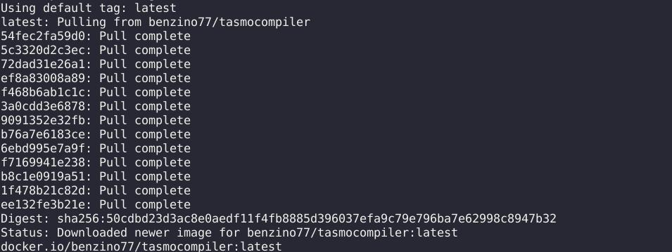
docker pull benzino77/tasmocompiler
If you run into permission issues, either append sudo to any docker command or create and add your current user to a docker group, as follows: sudo groupadd docker && sudo usermod -aG docker $USER. Other post-install configurations for Linux users can be found at the official docs: Optional post-install steps.
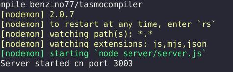
Then, run the tasmocompiler container, as follows:
docker run \
  --rm \
  --name tasmocompiler \
  -p 3000:3000 \
  -e DEBUG=server,git,compile \
  benzino77/tasmocompiler
Of course, if you use Portainer or other application for managing your docker containers, you can also pull and run tasmocompiler via the application instead of a terminal. In this case, translate the commands to your application. This also applies to users who are not running Docker on Linux.
This will create a container named tasmocompiler that has a web GUI exposed on port 3000 of the local machine. To access it, go to the following address using any web-browser:
Customizing the tasmota32-webcam firmware
Now that the tasmocompiler container is running, we can compile a new customized Tasmota firmware for the ESP32-cam in just a few simple steps:
-
Open any web-browser and navigate to http://localhost:3000;
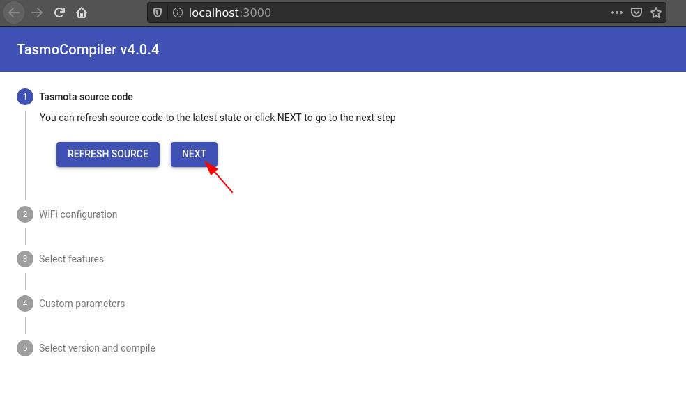
-
In Tasmota source code, select Refresh Source (this can take a few minutes, depending on your connection) and afterwards, Next;
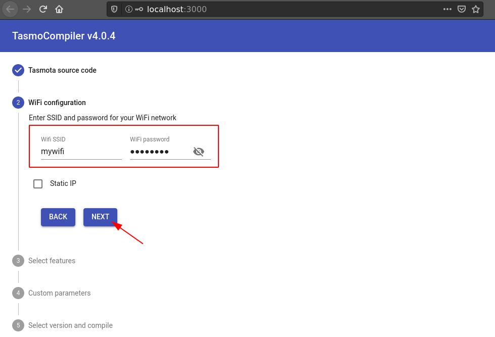
-
In WiFi configuration, add your wifi credentials and hit Next;
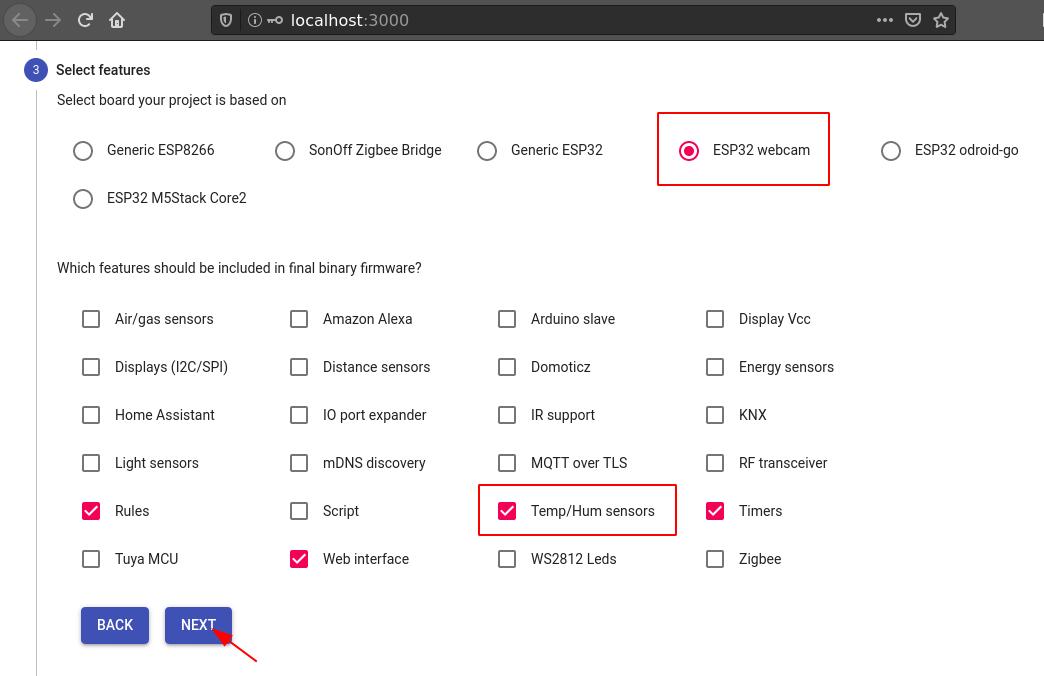
-
In Select Features, select ESP32 webcam as your board. For this example, we are adding the BME280 sensor module and therefore, in feature, we add the Temp/Hum sensors feature to support the BME280 sensor. If you are attaching another device, check the appropriate feature to support it here (e.g., check Displays (I2C/SPI) to support an OLED display module). When done, hit Next;
-
It is not necessary to edit any parameter in Custom Parameters, so hit Next;
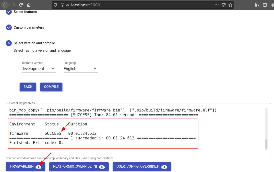
-
Finally, in Select Version and Compile, choose a Tasmota version (development is usually fine but if you run into issues later on, try the latest stable) and base language for the interface. Then, select Compile and wait until it is done (this can take a few minutes);


-
Once it is done compiling, check that the firmware was successfully compiled and if all looks good, download the firmware (and optionally, any of the other files);
If you run into issues, check the issues tab of the TasmoCompiler repository for open and closed issues similar to the one you are experiencing. If you do not find anything similar, open a new issue there to warn the developer know about it.
Updating the firmware
If you have already flashed a pre-compiled Tasmota binary onto the ESP32-cam, then it is possible to update the firmware over-the-air (OTA). To update the firmware OTA, do the following:
-
Open a web-browser and go to the IP address of your Tasmota ESP32-cam;
-
Then navigate to Firmware Upgrade > Upgrade by file upload > Browse and select the
firmware.binfile you compiled with TasmoCompiler. Afterwards, select Start Upgrade and wait until it is done; -
The device will reboot automatically and once it is back on, it should connect to the wireless network configured with TasmoCompiler.
Now, if you have not flashed any pre-compiled Tasmota binary, simply switch the tasmota32-webcam.factory.bin file mentioned in Flashing Tasmota32 webcam server for the firmware.bin file you compiled with TasmoCompiler.
Wiring and template configuration
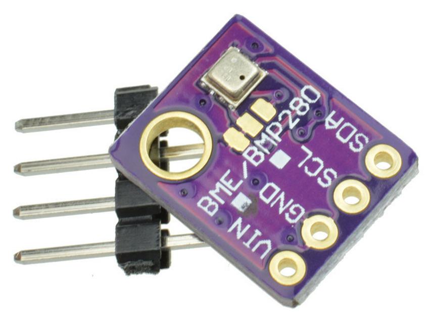
Suppose we have a BME280 sensor module wired to an ESP32-cam (AI-Thinker) board as follows:

Note that to use the VCC output pin as a 3.3V output pin, you need to make sure the board has a resistor connecting the two 3v3 pads and nothing connecting the two 5V pads. This was indicated by the red arrow in the image above. From my experience, a resistor connecting the 3v3 pads is the default for all ESP32-cam AI-Thinker boards, meaning that it should output 3.3V by default and if you want to change it to 5V, you need to desolder the resistor between the 3v3 pads and solder it between the 5V pads. However, make sure to double check this before wiring any peripheral that will use the VCC out pin from the board.
Then, now that the board is running a customized firmware that should support the BME280 sensor module, all that we need to do is to configure its template to inform the program about (a) which GPIO pins the peripheral is using and (b) how the pins should be configured.
To configure the ESP32-cam template, do the following:
-
Open a web-browser and go to the IP address of your Tasmota ESP32-cam;
-
Follow the instructions in Updating the template if you have not done that before. Afterwards, navigate to Configuration > Configure Other > Other parameters > Template and make sure the Activate is checked.
-
Navigate to Configuration > Configure Template. The name of the template should be the same one you specified in the previous step. Remember that according to the wiring of the BME280 board, SDA and SCL are connected to pins GPIO14 and GPIO15, respectively. Therefore, find the GPIO14 pin and instead of
User, selectI2C SDA; and similarly, find the GPIO15 pin and instead ofUser, selectI2C SCL.Currently, the default template for the ESP32-cam assigns SPI related components to
GPIO2,GPIO14, andGPIO15, as well as theSDCard CScomponent toGPIO13. If you are not using the micro-SD card, you can free-up all such pins by assigning theUsercomponent to them and then use them according to the needs of your peripherals. Be sure to test them thoroughly before sending the device to production because I’ve had a few issues with other pins that are supposedly safe to use–namely,GPIO12andGPIO16both causing boot loops.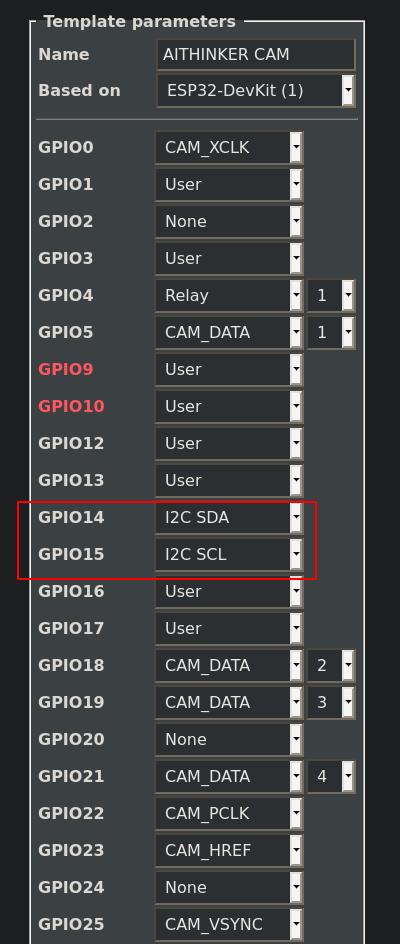
-
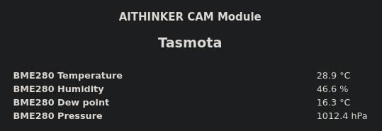
Hit Save and wait for the device to reboot. Once it comes back on, the firmware should automatically detect and configure the I2C device and on the Main Page, there should be some of the metrics associated with the device. Because we are connecting the board to a BME280 sensor module, the Main page will show measures for the ambient temperature, humidity, dew point, and pressure.
Of course, different peripherals will show different metrics, buttons, sliders, etc., on the main page. As before, the camera stream should be available on the main page and via port
81at/streamand/cam.mjpeg.
Conclusion
This concludes the tutorial on how to install and configure the Tasmota32 webcam server onto the ESP32-cam. As usual, if you spot an error or want to share an idea, feel free to get in touch with me. I try to keep my articles updated as much as possible to reflect my current understanding about the topic. All such updates are noted in the changelog.